Infiniti Q45. Manual - part 260


  Index      Infiniti     Infiniti Q45 - service repair manual 2006 year


Search            copyright infringement  


Content   ..  258  259  260  261   ..


Infiniti Q45. Manual - part 260


PREPARATION

BRC-5

[VDC/TCS/ABS]

C

D

E

G

H

I

J

K

L

M

A

B

BRC

PREPARATION

PFP:00002

Special Service Tools

NFS000CH

The actual shapes of Kent-Moore tools may differ from those of special service tools illustrated here.

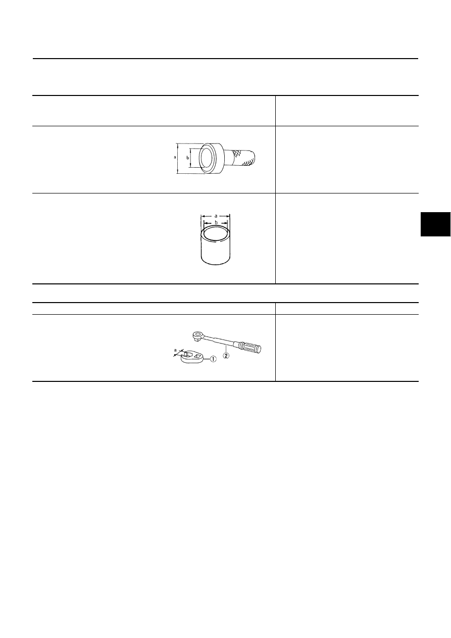
Commercial Service Tools

NFS000CI

Tool number 
(Kent-Moore No.)
Tool name

Description

ST30720000
(J-25405)
Drift
a: 77 mm (3.03 in) dia.
b: 55.5 mm (2.19 in) dia.

Installing rear sensor rotor.

ST27863000
(

)

Drift
a: 74.5 mm (2.93 in) dia.
b: 62.5 mm (2.46 in) dia.

KV40104710
(

)

Drift
a: 76.3 mm (3.00 in) dia.
b: 67.9 mm (2.67 in) dia.

Installing rear sensor rotor.

ZZC0760D

ZZA0832D

Tool name

Description

1.Flare nut crowfoot
 a:10 mm (0.39 in)/12 mm (0.47 in)
2.Torque wrench

Removing and installing each brake piping

S-NT360

BRC-6

[VDC/TCS/ABS]

ON-VEHICLE SERVICE

ON-VEHICLE SERVICE

PFP:00000

Adjustment of Steering Angle Sensor Neutral Position

NFS000CJ

In case of doing work that applies to the list below, make sure to adjust neutral position of steering angle sen-
sor before running vehicle.

×

: Required

–: Not required

CAUTION:

To adjust neutral position of steering angle sensor, make sure to use CONSULT-II.
(Adjustment cannot be done without CONSULT-II.)

1.

Stop vehicle with front wheels in straight-ahead position.

2.

Perform “CONSULT-II Start Procedure”. Refer to 

GI-36, "CONSULT-II Start Procedure"

 .

3.

Touch “WORK SUPPORT”.

4.

Touch “START”on“ST ANGLE SENSOR ADJUSTMENT”screen.

CAUTION:

Do not touch steering wheel while adjusting steering angle
sensor.

5.

After approximately 10 seconds, touch “END”. (After approxi-
mately 60 seconds, it ends automatically.)

6.

Turn ignition switch OFF, then turn it ON again.

CAUTION:

Be sure to perform above operation.

7.

Run vehicle with front wheels in straight-ahead position, then
stop.

8.

Select “DATA MONITOR”, “ECU INPUT SIGNALS”, and “STR ANGLE SIG” on CONSULT-II screen. Then
make sure that “STR ANGLE SIG” is within 0 

±

2.5

°

. If value is more than specification, repeat steps 1 to 7.

9.

Erase memory of VDC/TCS/ABS control unit and ECM. Refer to 

BRC-26, "How to Erase Self-Diagnostic

Results"

 , 

EC-82, "TROUBLE DIAGNOSIS"

 .

10. Turn ignition switch OFF.

Situation

Adjustment of Steering Angle Sensor Neutral Position 

Removing/Installing VDC/TCS/ABS control unit

Replacing VDC/TCS/ABS control unit

×

Removing/Installing steering angle sensor

×

Removing/Installing steering components

×

Removing/Installing suspension components

×

Change tires to new ones

Tire rotation

Adjusting wheel alignment

×

SFIA1659E

SYSTEM DESCRIPTION

BRC-7

[VDC/TCS/ABS]

C

D

E

G

H

I

J

K

L

M

A

B

BRC

SYSTEM DESCRIPTION

PFP:00000

System Diagram

NFS000CK

COMPONENTS FUNCTION DESCRIPTION

Functions

NFS000CL

VDC

In addition to TCS/ABS function, VDC detects driver's steering operation amount and brake pedal travel
from steering angle sensor and pressure sensor. Using information from yaw rate/side G sensor and
wheel sensor, VDC judges driving condition (conditions of under steer and over steer) to improve stability
by controlling brake application to 4 wheels and engine output.

During VDC operation, SLIP indicator lamp flashes to inform driver of VDC operation.

Electrical system diagnosis by CONSULT-II is available.

PFIA0692E

Component

Description

VDC/TCS/ABS control unit

Receives the information of various sensor signals, ECM and TCM, and then determines the vehi-
cle driving status. Performs the calculations of target brake fluid pressure, by VDC actuator drive 
signal output and by engine torque required from the VDC/TCS/ABS control.

VDC actuator

Receives the actuator drive signal from VDC/TCS/ABS control unit, and then performs the brake 
fluid adjustment of each wheel caliper.

Yaw rate/side G sensor

Detects the yaw rate and side G of the vehicle.

Steering angle sensor

Detects the operating angle and direction of driver steering wheel.

Pressure sensor
(Integrated in VDC actuator)

Detects the fluid pressure (driver brake force) in VDC actuator.

Wheel sensor

Detects the rotation speed of each wheel.

VDC OFF switch

Cancels the VDC/TCS function.

ECM

Receives the command from VDC/TCS/ABS control unit, and then performs the controls of throttle 
motor and injector.

BRC-8

[VDC/TCS/ABS]

SYSTEM DESCRIPTION

TCS

VDC/TCS/ABS control unit detects a spin at drive wheels by comparing wheel speed signals from all 4
wheels. At this time, output from control unit controls brake fluid pressure to both LH and RH rear wheels
while cutting fuel to engine and closing throttle valve to reduce engine torque. Furthermore, throttle posi-
tion is continuously controlled to insure appropriate engine torque at all times.

During TCS operation, it informs driver of system operation by flashing SLIP indicator lamp.

Electrical system diagnosis by CONSULT-II is available.

ABS

The Anti-Lock Brake System is a function that detects wheel revolution while braking, and it improves
handling stability during sudden braking by electrically preventing 4 wheels lock. Maneuverability is also
improved for avoiding obstacles.

Electrical system diagnosis by CONSULT-II is available.

EBD

Electronic Brake Distribution is a function that detects subtle slippages between the front and rear tire dur-
ing braking, and it improves handling stability by electronically controlling the brake fluid pressure which
results in reduced rear tire slippage.

Electrical system diagnosis by CONSULT-II is available.

Operation that is not “System Error”

NFS000CM

VDC

During VDC operation, body and brake pedal lightly vibrate and mechanical noises may be heard. This is
normal.

If vehicle is rotated on turn table, or rolled and rocked on ship, ABS warning lamp, VDC OFF indicator
lamp and SLIP indicator lamp may turn on. In this case, start engine on normal road again. If ABS warning
lamp, VDC OFF indicator lamp, and SLIP indicator lamp turn off after restart, it is normal.

When starting TCS or VDC under rapid acceleration or hard turn, operating noise by brake pedal is gener-
ated. However, this is not something wrong. This is because TCS and VDC are functioning normally. 

When driving in steep slope such as bank, ABS warning lamp, VDC OFF indicator lamp, and SLIP indica-
tor lamp may turn on. In this case, start engine on normal road again. If ABS warning lamp, VDC OFF indi-
cator lamp and SLIP indicator lamp turn off after restart, it is normal.

A malfunction oriented Yaw rate / side G sensor may occur under hard turn like spin turn, rapid accelera-
tion turn, drift run, etc. when VDC function is OFF (VDC OFF switch on). It is not something wrong if it is
possible to return to a normal position after restarting engine. Then erase the memory of Self-Diagnosis.
Refer to 

BRC-26, "How to Erase Self-Diagnostic Results"

 .

TCS

During TCS operation, body and brake pedal lightly vibrate and mechanical noises may be heard. This is
normal.

Depending on road circumstances, driver may have a sluggish feel. This is normal, because optimum
traction has highest priority under TCS operation.

When vehicle is passing through a road where surface friction coefficient varies, downshifting or depress-
ing accelerator pedal fully may activate TCS temporarily.

ABS

When starting engine or just after starting vehicle, brake pedal may vibrate or the motor operating noise
may be heard from engine room. This is a normal states of the operation check.

During ABS operation, brake pedal lightly vibrates and a mechanical noise may be heard. This is normal.

Stopping distance may be longer than that of vehicles without ABS when vehicle drives on rough, gravel,
or snow-covered (fresh, deep snow) roads.


Content   ..  258  259  260  261   ..