Infiniti Q45. Manual - part 251


  Index      Infiniti     Infiniti Q45 - service repair manual 2006 year


Search            copyright infringement  


Content   ..  249  250  251  252   ..


Infiniti Q45. Manual - part 251


NOISE, VIBRATION AND HARSHNESS (NVH) TROUBLESHOOTING

BR-5

C

D

E

G

H

I

J

K

L

M

A

B

BR

NOISE, VIBRATION AND HARSHNESS (NVH) TROUBLESHOOTING

PFP:00003

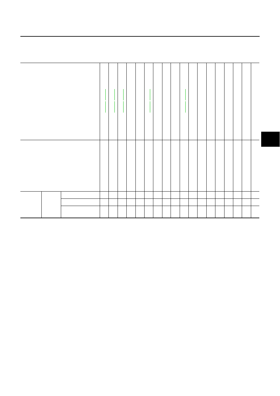
NVH Troubleshooting Chart

NFS000B7

Use the chart below to help you find the cause of the symptom. If necessary, repair or replace these parts.

X: Applicable

Reference page

BR-

2

3

,

BR-

2

9

BR-

2

3

,

BR-

2

9

BR-

2

3

,

BR-

2

9

BR-

2

8

,

BR-

3

3

BR-

2

8

,

BR-

3

3

N

V

H in

 PR s

e

c

ti

o

n

N

V

H in

 RFD s

e

c

ti

o

n

N

V

H in

 F

AX, RAX 

a

n

d

 FS

U

RSU s

e

c

ti

o

n

N

V

in

 W

T

 s

e

c

tio

n

N

V

in

 W

T

 s

e

c

tio

n

N

V

H in

 RAX s

e

c

ti

o

n

N

V

H in

 PS s

e

c

tio

n

Possible cause and
SUSPECTED PARTS

Pad

s

 -

 dam

age

d

Pad

s

 -

 unev

en w

ear

Shi

m

s dam

ag

ed

R

o

to

r i

m

bal

anc

e

Ro

to

r d

a

ma

g

e

R

o

to

r r

un 

out

Ro

to

r d

e

fo

rm

a

ti

o

n

R

o

to

r d

e

fl

e

c

ti

o

n

Ro

to

r ru

s

t

R

o

to

r t

h

ickn

ess 

va

ri

at

io

n

D

rum

 ou

of

 r

oun

d

PROPELL

E

R SHAF

T

DIFFERENTIAL

AXL

E AND 

SUSPENSION

TIRES

ROAD W

H

EEL

D

R

IV

E

 SH

AF

T

STEERING

Symptom

BRAKE

Noise

×

×

×

×

×

×

×

×

×

×

Shake

×

×

×

×

×

×

×

Shimmy, Judder

×

×

×

×

×

×

×

×

×

×

×

BR-6

BRAKE PEDAL

BRAKE PEDAL

PFP:46501

Inspection and Adjustment

NFS000B8

PLAY AND CLEARANCE BETWEEN BRAKE PEDAL AND FLOOR PANEL WITH PEDAL 
DEPRESSED

Check brake pedal play.

Check brake pedal free height from dash lower panel.

Adjust height referring to following specifications.

SFIA2427E

H

Brake pedal height (from dash lower panel top surface)

192.4 – 202.4 mm (7.57 –7.97 in)

D

Depressed pedal height [under a force of 490 N (50 kg, 
110 lb) with engine running]

90 mm (3.54 in) or more

C

Clearance between stopper rubber and threaded end of 
stop lamp switch and ASCD cancel switch.

0.74 – 1.96 mm (0.0291 – 0.0772 in)

A

Pedal play

3 – 11 mm (0.12 – 0.43 in)

BRAKE PEDAL

BR-7

C

D

E

G

H

I

J

K

L

M

A

B

BR

ADJUSTMENT 

1.

Loosen stop lamp switch and ASCD cancel switch by rotating it
counterclockwise by 45

°

.

2.

Loosen lock nut (A) on input rod to rotate input rod for adjusting
brake pedal height to the specified one, and tighten lock nut (A).
Refer to 

BR-20, "Components"

 .

CAUTION:

Make sure the threaded end of input rod stays inside clevis.

3.

With the pedal pulled and held by hand, press stop lamp switch
and ASCD cancel switch until its threaded end contacts stopper
rubber.

4.

With the threaded end of stop lamp switch and ASCD cancel
switch contacting the bracket, rotate switch clockwise by 45

°

 to

secure.

CAUTION:

Make sure that clearance (C) between stopper rubber and
end of stop lamp switch and ASCD cancel switch is within
the standard.

5.

Check pedal play. Refer to 

BR-6, "Inspection and Adjustment"

 .

CAUTION:

Make sure that stop lamps go off when pedal is released.

6.

Start the engine to check brake pedal depression height when
depressed. Refer to 

BR-6, "Inspection and Adjustment"

 .

Components

NFS000HY

SFIA0160E

1.

Clevis pin

2.

Brake pedal stroke sensor

3.

Snap pin

4.

ASCD cancel switch

5.

Stop lamp switch

6.

Clip

7.

Stopper rubber

8.

Brake pedal assembly

9.

Brake pedal pad

SFIA2469E

BR-8

BRAKE PEDAL

Removal and Installation

NFS000B9

REMOVAL 

1.

Remove instrument lower driver panel. Refer to 

IP-16, "(V)

Instrument Lower Driver Panel"

 .

2.

Remove steering column. Refer to 

PS-11, "STEERING COL-

UMN"

 .

3.

Remove stop lamp switch and ASCD cancel switch from brake
pedal assembly.

4.

Disconnect the brake pedal stroke sensor connector.

CAUTION:

Brake pedal stroke sensor is not detachable. Do not detach
it.

5.

Remove snap pin and clevis pin from brake booster clevis.

6.

Remove mounting nuts and bolt from bracket, and remove brake pedal assembly from vehicle.

INSPECTION AFTER REMOVAL 

Check brake pedal upper rivet for deformation.

Make sure that the lapping length of sub-bracket and slide plate
is at least 5 mm (0.20 in).

Check brake pedal for bend, damage, and cracks on the welded
parts.

Replace brake pedal assembly if any non-standard condition is
detected.

Check clevis pin and plastic stopper for damage and deforma-
tion. Replace clevis pin if there are.

INSTALLATION 

Paying attention to the following, install in the reverse order of the removal.
Tighten the mounting nuts and bolt to the specified torque. Refer to 

BR-7, "Components"

 .

After installing brake pedal assembly to vehicle, adjust brake pedal. Refer to 

BR-6, "Inspection and

Adjustment"

 .

SFIA0159E

SFIA2289E

SBR997


Content   ..  249  250  251  252   ..