Infiniti Q45. Manual - part 207
REMOTE KEYLESS ENTRY SYSTEM
BL-97
C
D
E
F
G
H
J
K
L
M
A
B
BL
3.
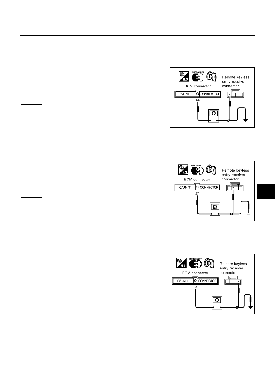
CHECK REMOTE KEYLESS ENTRY RECEIVER HARNESS
1.
Disconnect BCM and remote keyless entry receiver connector.
2.
Check continuity between BCM connector M4 terminal 44 and remote keyless entry receiver connector
B246 terminal 1.
3.
Check continuity between BCM connector M4 terminal 44 and
ground.
OK or NG
OK
>> Remote keyless entry receiver circuit is OK.
NG
>> Repair or replace harness.
4.
CHECK REMOTE KEYLESS ENTRY RECEIVER HARNESS
1.
Disconnect BCM and remote keyless entry receiver connector.
2.
Check continuity between remote keyless entry receiver connector B246 terminal 2 and BCM connector
M4 terminal 27.
3.
Check continuity between BCM connector M4 terminal 27 and
ground.
OK or NG
OK
>> Replace remote keyless entry receiver.
NG
>> Repair or replace harness.
5.
CHECK REMOTE KEYLESS ENTRY RECEIVER HARNESS
1.
Disconnect BCM and remote keyless entry receiver connector.
2.
Check continuity between BCM connector M4 terminal 28 and remote keyless entry receiver connector
B246 terminal 4.
3.
Check continuity between remote keyless entry receiver con-
nector B246 terminal 4 and ground.
OK or NG
OK
>> Replace BCM.
NG
>> Repair or replace harness.
44 (Y) – 1 (Y)
: Continuity should exist.
44 (Y) – Ground
: Continuity should not exist.
PIIA3081E
27 (BR/W) – 2 (BR/W)
: Continuity should exist.
27 (BR/W) – Ground
: Continuity should not exist.
PIIA3082E
28 (L) – 4 (L)
: Continuity should exist.
28 (L) – Ground
: Continuity should not exist.
PIIA3083E