Index Infiniti Infiniti Q45 - service repair manual 2006 year
Search copyright infringement
Content .. 188 189 190 191 ..
Infiniti Q45. Manual - part 190
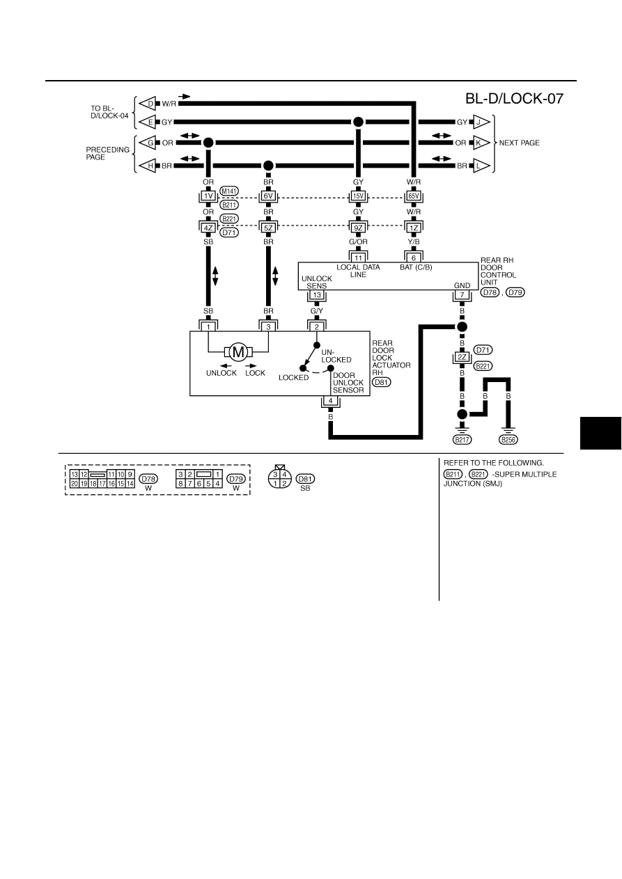
POWER DOOR LOCK SYSTEM
BL-29
C
D
E
F
G
H
J
K
L
M
A
B
BL
TIWM1546E