Index Infiniti Infiniti Q45 - service repair manual 2006 year
Search copyright infringement
Content .. 177 178 179 180 ..
Infiniti Q45. Manual - part 179
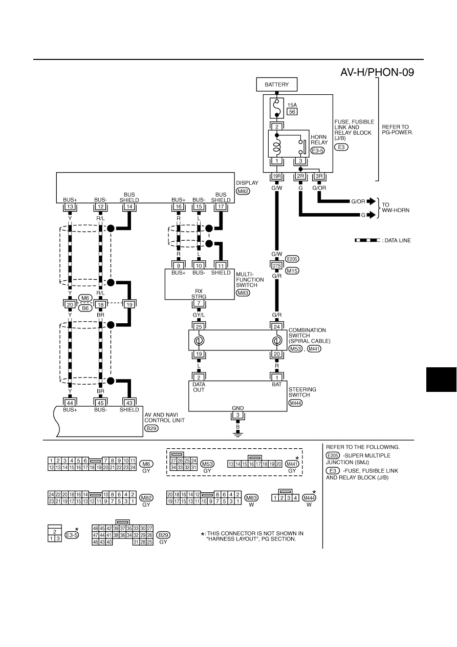
TELEPHONE
AV-145
C
D
E
F
G
H
I
J
L
M
A
B
AV
TKWM3832E