Infiniti Q45. Manual - part 174
NAVIGATION SYSTEM
AV-125
C
D
E
F
G
H
I
J
L
M
A
B
AV
RGB Image Is Rolling
NKS001J8
Symptom: RGB image such as a map screen is rolling.
1.
CHECK HARNESS
1.
Turn ignition switch OFF.
2.
Disconnect AV and NAVI control unit and display connectors.
3.
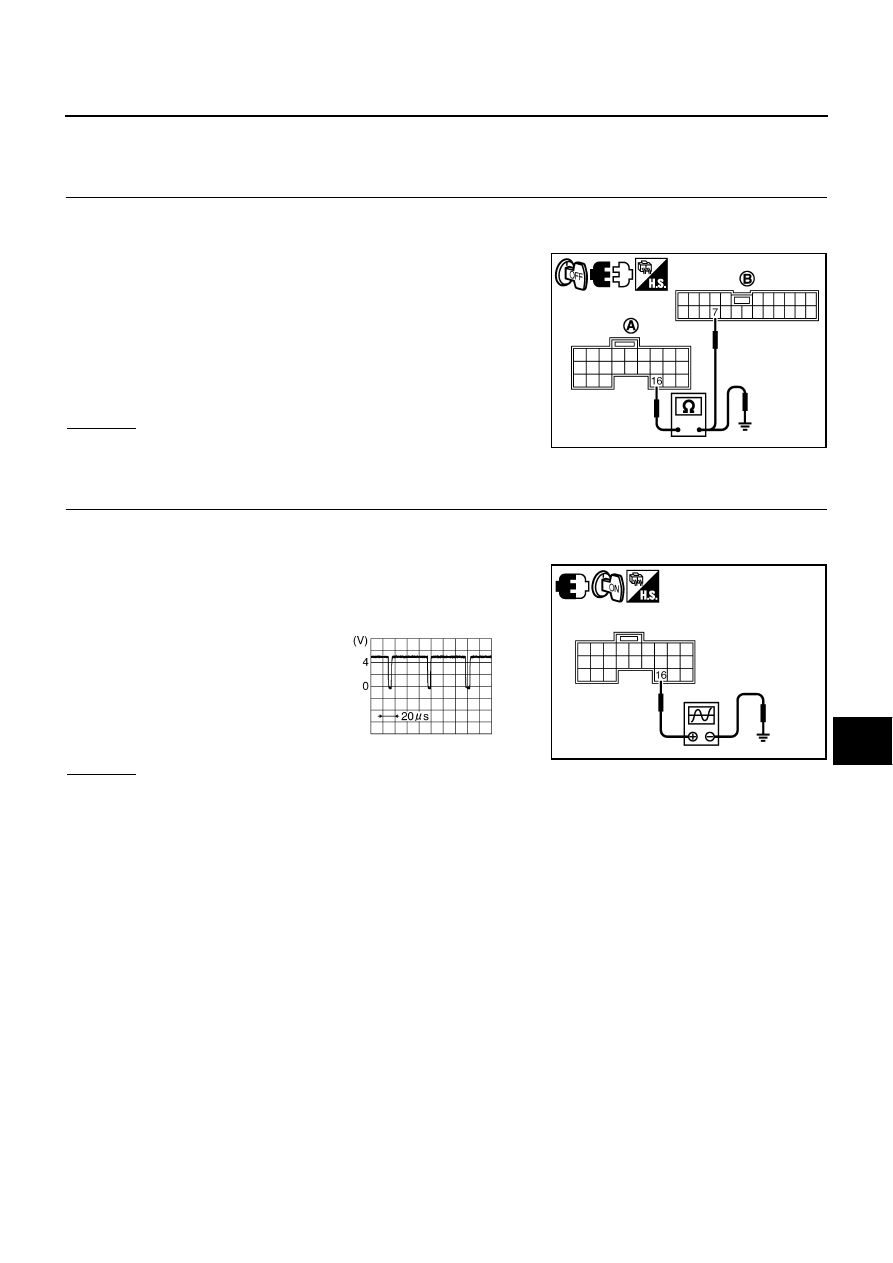
Check continuity between AV and NAVI control unit harness
connector (A) B30 terminal 16 and display harness connector
(B) M82 terminal 7.
4.
Check continuity between AV and NAVI control unit harness
connector (A) B30 terminal 16 and ground.
OK or NG
OK
>> GO TO 2.
NG
>> Repair harness or connector.
2.
CHECK RGB SYNCHRONIZING SIGNAL
1.
Connect AV and NAVI control unit and display connectors.
2.
Turn ignition switch ON.
3.
When displaying RGB image, check voltage waveform between
AV and NAVI control unit harness connector B30 terminal 16
and ground with CONSULT-ll or oscilloscope.
OK or NG
OK
>> Replace display.
NG
>> Replace AV and NAVI control unit.
16 – 7
: Continuity should exist.
16 – Ground
: Continuity should not exist.
SKIB7662E
16 – Ground:
SKIB7663E
SKIB3603E