Infiniti Q45. Manual - part 171


  Index      Infiniti     Infiniti Q45 - service repair manual 2006 year


Search            copyright infringement  


Content   ..  169  170  171  172   ..


Infiniti Q45. Manual - part 171


NAVIGATION SYSTEM

AV-113

C

D

E

F

G

H

I

J

L

M

A

B

AV

NAVIGATION
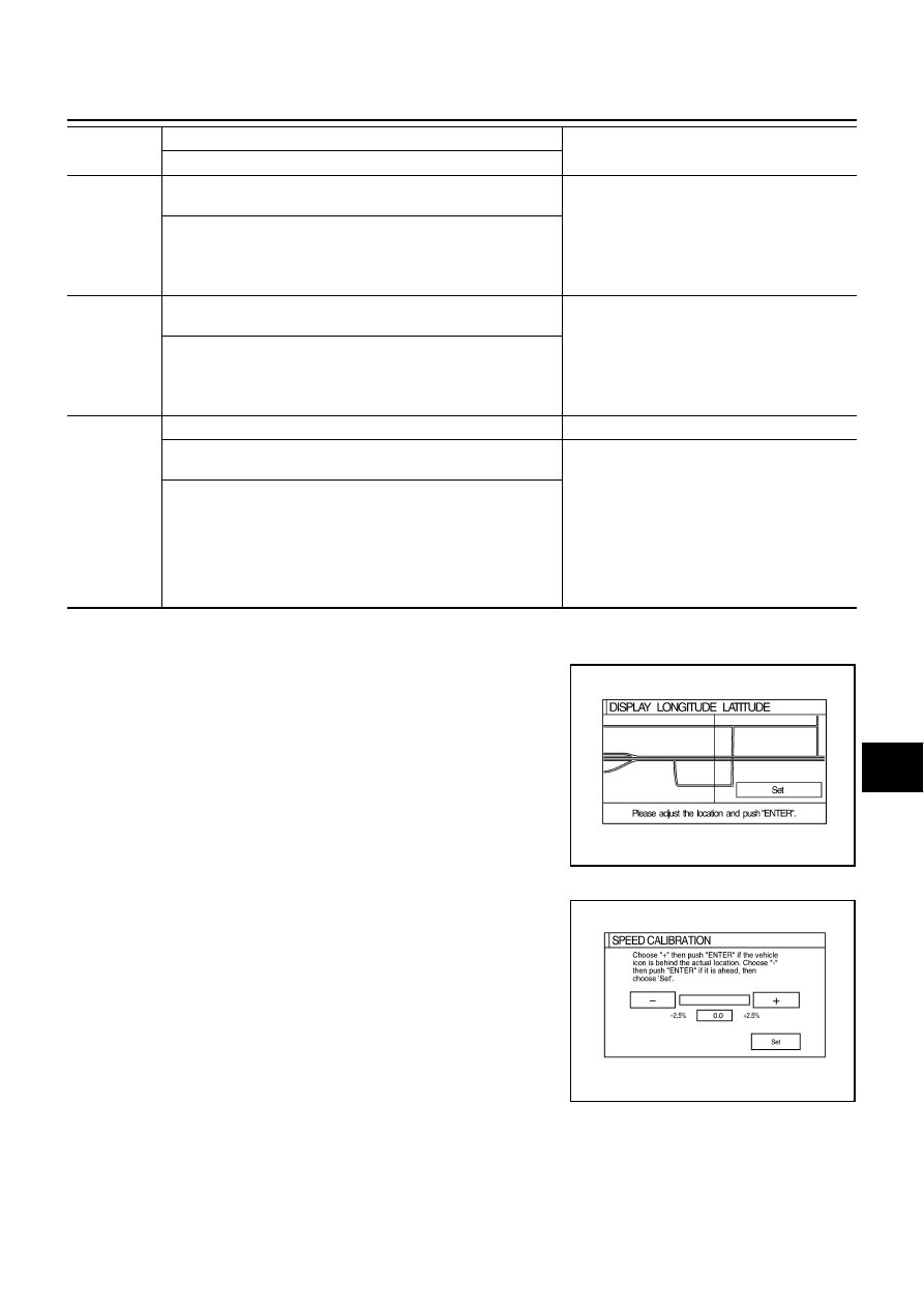
Display Longitude & Latitude

Able to confirm/adjust longitude and latitude.

Speed Calibration

During normal driving, distance error caused by tire wear and tire
pressure change is automatically adjusted for by the automatic dis-
tance correction function. Speed calibration function, on the other
hand, is for immediate adjustment, in cases such as driving with tire
chain fitted on tires.

GPS antenna 
disconnected

Malfunctioning connection between GPS substrate in AV and NAVI 
control unit and GPS antenna.

Navigation location detection performance 
has deteriorated.
(Location correction using GPS is not per-
formed.)

GPS receiving status remains gray.

Perform self-diagnosis.

When connection between AV and NAVI control unit and GPS 
antenna is judged normal by self-diagnosis, the symptom may 
be intermittent, caused by impact or vibration.

Low voltage 
of GPS

The power voltage supplied to the GPS circuit board has 
decreased.

Navigation location detection performance 
has deteriorated.
(Location correction using GPS is not per-
formed.)

GPS receiving status remains gray.

Perform self-diagnosis.

When connection between AV and NAVI control unit and GPS 
antenna is judged normal by self-diagnosis, the symptom may 
be intermittent, caused by impact or vibration.

DVD-ROM 
malfunction
DVD-ROM 
read error
DVD-ROM 
response 
Error

Malfunctioning AV and NAVI control unit.

Dedicated DVD-ROM is in the system, but the data cannot be 
read.

The map of a particular location cannot be dis-
played.

Specific guidance information cannot be dis-
played.

Map display is slow.

Guidance information display is slow.

System has been affected by vibration.

Is DVD-ROM damaged, warped, or dirty?

If damaged or warped, the DVD-ROM is malfunctioning.

If dirty, wipe the DVD-ROM clean with a soft cloth.

Perform self-diagnosis.

When AV and NAVI control unit is judged normal by self-diagno-
sis, the symptom is judged intermittent, caused by vibration.

Error item

Possible causes

Example of symptom

Action/symptom

SKIA4575E

SKIA0365E

AV-114

NAVIGATION SYSTEM

Angle Adjustment

The turning angle output detected by the gyroscope can be adjusted.

Initialize Location

This mode is for initializing the current location.

SKIA0364E

NAVIGATION SYSTEM

AV-115

C

D

E

F

G

H

I

J

L

M

A

B

AV

CONSULT-II Function (MULTI AV)

NKS001J0

CONSULT-II can display each diagnostic item using the diagnostic test modes shown following.

CONSULT-II BASIC OPERATION PROCEDURE

Refer to 

GI-36, "CONSULT-II Start Procedure"

 .

VERSION

Displays version of each unit connected to the AV and NAVI control unit.

System part

Diagnosis mode

Description

MULTI AV

VERSION

Displays version of each unit connected to AV and NAVI control unit.

SELF-DIAG RESULTS

Performs the connection diagnosis of communication circuit between AV and NAVI control 
unit and each unit, and displays the current malfunctions.

The DVD-ROM drive diagnosis of AV and NAVI control unit can be performed.

SIGNAL MONITOR

The diagnosis of vehicle signal that is input to the AV and NAVI control unit can be per-
formed.

SKIB0654E

Version display

Remarks

“PANEL SW”

Multifunction switch

“MAP DISK”

DVD-ROM

“HEAD UNIT”

AV and NAVI control unit

“FRONT SEAT DISPLAY”

Display

“AUDIO HEAD UNIT”

Audio unit

“AIR COMP RECEIVER”

Low tire pressure warning control unit

“BOSE AMP”

BOSE speaker amp.

“VOICE UNIT”

Voice activated control module

AV-116

NAVIGATION SYSTEM

SELF-DIAG RESULTS

The self-diagnosis is started and self-diagnosis results are displayed by touching “START” after selecting
“SELF-DIAG RESULTS”.

Display Item of SELF-DIAG RESULTS

Self-diagnosis results may be displayed simultaneously according to the cause. If some error items are dis-
played simultaneously, the detection of the cause can be performed by the combination of display items.

NOTE:
When “IVCS [ABNORMAL CONNECTION]” is indicated, this is not malfunction.

Error item

Possible cause

Action to take

HEAD UNIT
[ABNORMAL]

AV and NAVI control unit malfunction is 
detected

Replace AV and NAVI control unit

BOSE AMP
[ABNORMAL]

BOSE speaker amp. malfunction is 
detected

Replace BOSE speaker amp.

VOICE UNIT
[ABNORMAL]

Voice activated control module malfunction 
is detected

Replace voice activated control module

MAP DISC
[NO INSERT]

DVD-ROM not inserted is detected

Insert DVD-ROM

MAP DISC
[ABNORMAL]

Malfunction is detected on DVD-ROM 
drive pickup lens in AV and NAVI control 
unit

There is dirt and damage on the DVD-
ROM

1. Check if the inserted DVD-ROM is specified for this 

navigation system, and the DVD-ROM is dirty, 
scratched or warped.

2. If the results from the above checkup show no mal-

function, insert the same DVD-ROM, and then 
restart self-diagnosis.

3. If self-diagnosis results still show any malfunction, 

replace AV and NAVI control unit.

MAP DISC DRIVER
[ABNORMAL 1]

MAP DISC OR DRIVER
[ABNORMAL]

PANEL SW
[ABNORMAL CONNECTION]

AUDIO HEAD UNIT
[ABNORMAL CONNECTION]

AIR COMP RECEIVER
[ABNORMAL CONNECTION]

VOICE UNIT
[ABNORMAL CONNECTION]

BOSE AMP
[ABNORMAL CONNECTION]

FRONT SEAT DISPLAY
[ABNORMAL CONNECTION]

Malfunction is detected on communication 
signal

Check all communication circuits composing AV sys-
tem. Repair malfunctioning parts.

PANEL SW
[ABNORMAL CONNECTION]

AUDIO HEAD UNIT
[ABNORMAL CONNECTION]

AIR COMP RECEIVER
[ABNORMAL CONNECTION]

BOSE AMP
[ABNORMAL CONNECTION]

FRONT SEAT DISPLAY
[ABNORMAL CONNECTION]

Malfunction is detected on communication 
signal between AV and NAVI control unit 
and display

1. Check communication circuit between AV and NAVI 

control unit and display.

2. If the results from the above checkup show no mal-

function, replace either AV and NAVI control unit or 
display, and then start self-diagnosis.

3. If self-diagnosis results still show any malfunction, 

replace the other unit.

PANEL SW
[ABNORMAL CONNECTION]

AUDIO HEAD UNIT
[ABNORMAL CONNECTION]

AIR COMP RECEIVER
[ABNORMAL CONNECTION]

BOSE AMP
[ABNORMAL CONNECTION]

Malfunction is detected on communication 
signal between display and multifunction 
switch

1. Check communication circuit between display and 

multifunction switch.

2. If the results from the above checkup show no mal-

function, replace either display or display, and then 
start self-diagnosis.

3. If self-diagnosis results still show any malfunction, 

replace the other unit.


Content   ..  169  170  171  172   ..