Infiniti Q45. Manual - part 154


  Index      Infiniti     Infiniti Q45 - service repair manual 2006 year


Search            copyright infringement  


Content   ..  152  153  154  155   ..


Infiniti Q45. Manual - part 154


AUDIO

AV-45

C

D

E

F

G

H

I

J

L

M

A

B

AV

3. 

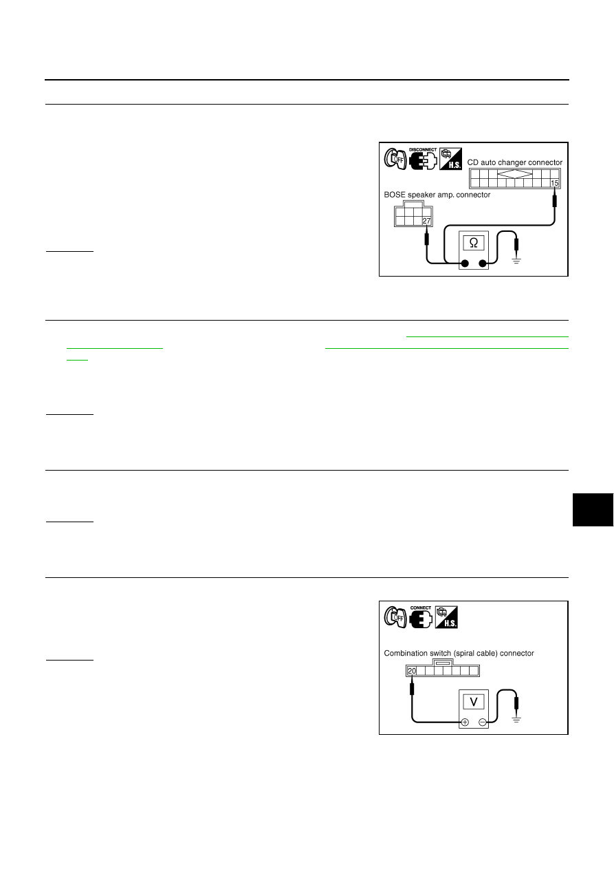
CHECK GROUND CIRCUIT

1.

Turn ignition switch OFF.

2.

Disconnect BOSE speaker amp. and CD auto changer connectors.

3.

Check continuity between BOSE speaker amp. harness connec-
tor B233 terminal 27 and ground.

4.

Check continuity between CD auto changer harness connector
M109 terminal 15 and ground.

OK or NG

OK

>> INSPECTION END

NG

>> Repair harness or connector.

Steering Switch Does Not Operate

NKS001I4

1. 

SELF-DIAGNOSIS MODE OF MULTIFUNCTION SWITCH

1.

Perform the self-diagnosis mode in the self-diagnosis function. Refer to 

DI-136, "Multifunction Switch Self-

Diagnosis Function"

  (Without navigation system), or 

DI-165, "Multifunction Switch Self-Diagnosis Func-

tion"

  (With navigation system).

2.

Press steering switch.

OK or NG

OK

>> GO TO 8.

NG

>> GO TO 2.

2. 

CHECK HORN OPERATION

Check horn operation.

OK or NG

OK

>> GO TO 5.

NG

>> GO TO 3.

3. 

CHECK POWER SUPPLY CIRCUIT

1.

Turn ignition switch OFF.

2.

Check voltage between combination switch (spiral cable) har-
ness connector M441 terminal 20 and ground.

OK or NG

OK

>> GO TO 5.

NG

>> GO TO 4.

27 – Ground

: Continuity should exist.

15 – Ground

: Continuity should exist.

SKIA9183E

Beep sound should operate.

Horn should operate.

20 – Ground

: Battery voltage

SKIA9155E

AV-46

AUDIO

4. 

CHECK SPIRAL CABLE

1.

Disconnect combination switch (spiral cable) connector.

2.

Check continuity between combination switch (spiral cable) con-
nector M53 terminal 24 and connector M441 terminal 20.

OK or NG

OK

>> Repair power supply circuit of horn system.

NG

>> Replace spiral cable.

5. 

CHECK HARNESS

1.

Turn ignition switch OFF.

2.

Disconnect steering switch and combination switch (spiral cable) connectors.

3.

Check continuity between steering switch harness connector
M444 terminals 1, 2 and combination switch (spiral cable) har-
ness connector M441 terminals 20, 19. 

4.

Check continuity between steering switch harness connector
M444 terminals 1, 2 and ground.

5.

Check continuity between steering switch harness connector
M444 terminal 3 and ground. 

OK or NG

OK

>> GO TO 6.

NG

>> Repair harness or connector.

6. 

CHECK SPIRAL CABLE

1.

Disconnect combination switch (spiral cable) connector.

2.

Check continuity between combination switch (spiral cable) con-
nector M53 terminal 25 and connector M441 terminal 19. 

OK or NG

OK

>> GO TO 7.

NG

>> Replace spiral cable.

24 – 20

: Continuity should exist.

SKIA9157E

1 – 20

: Continuity should exist.

2 – 19

: Continuity should exist.

1, 2 – Ground

: Continuity should not exist.

SKIA9158E

3 – Ground

: Continuity should exist.

SKIA9162E

25 – 19

: Continuity should exist.

SKIA9159E

AUDIO

AV-47

C

D

E

F

G

H

I

J

L

M

A

B

AV

7. 

CHECK HARNESS

1.

Disconnect multifunction switch connector.

2.

Check continuity between combination switch (spiral cable) har-
ness connector M53 terminal 25 and multifunction switch har-
ness connector M83 terminal 7.

3.

Check continuity between combination switch (spiral cable) har-
ness connector M53 terminal 25 and ground.

OK or NG

OK

>> GO TO 8.

NG

>> Repair harness or connector.

8. 

CHECK COMMUNICATION SIGNAL

1.

Connect steering switch, combination switch (spiral cable) and multifunction switch connectors.

2.

Turn ignition switch ON.

3.

Check voltage waveform between steering switch harness con-
nector M444 terminal 2 and ground with CONSULT-II or oscillo-
scope, when operating the steering switch.

OK or NG

OK

>> Replace multifunction switch.

NG

>> Replace steering switch.

Rear Control Switch Does Not Operate

NKS001I5

1. 

CONFIRM STATUS OF REAR CONTROL CANCEL SWITCH

Is rear control cancel switch in the status of cancel?

YES or NO

YES

>> After turning on the switch reconfirm the status.

NO

>> GO TO 2.

2. 

SELF-DIAGNOSIS MODE OF MULTIFUNCTION SWITCH

1.

Perform the self-diagnosis mode in the self-diagnosis function. Refer to 

DI-136, "Multifunction Switch Self-

Diagnosis Function"

  (Without navigation system), or 

DI-165, "Multifunction Switch Self-Diagnosis Func-

tion"

  (With navigation system).

2.

Press rear control switch.

OK or NG

OK

>> GO TO 12.

NG

>> GO TO 3.

25 – 7

: Continuity should exist.

25 – Ground

: Continuity should not exist.

SKIA9160E

2 – Ground:

SKIA9165E

SKIB0382E

Beep sound should operate.

AV-48

AUDIO

3. 

CHECK POWER SUPPLY CIRCUIT

1.

Turn ignition switch ON.

2.

Check voltage between rear control cancel switch harness con-
nector R16 terminal 4 and ground.

OK or NG

OK

>> GO TO 4.

NG

>> Repair harness or connector.

4. 

CHECK REAR CONTROL CANCEL SWITCH

1.

Turn ignition switch OFF.

2.

Disconnect rear control cancel switch connector.

3.

Check continuity between rear control cancel switch terminals 3
and 4.

OK or NG

OK

>> GO TO 5.

NG

>> Replace rear control cancel switch.

5. 

 CHECK HARNESS

1.

Disconnect rear control cancel relay connector.

2.

Check continuity between rear control cancel switch harness
connector R16 terminal 3 and rear control cancel relay harness
connector B253 terminal 2.

3.

Check continuity between rear control cancel switch harness
connector R16 terminal 3 and ground.

OK or NG

OK

>> GO TO 6.

NG

>> Repair harness or connector.

4 – Ground

: Battery voltage

SKIB0383E

When press “ON”

: Continuity should exist.

When press “CANCEL”

: Continuity should not exist.

SKIB8683E

3 – 2

: Continuity should exist.

3 – Ground

: Continuity should not exist.

SKIA3660E


Content   ..  152  153  154  155   ..