Infiniti Q45. Manual - part 134


  Index      Infiniti     Infiniti Q45 - service repair manual 2006 year


Search            copyright infringement  


Content   ..  132  133  134  135   ..


Infiniti Q45. Manual - part 134


BLOWER UNIT

ATC-131

C

D

E

F

G

H

I

K

L

M

A

B

ATC

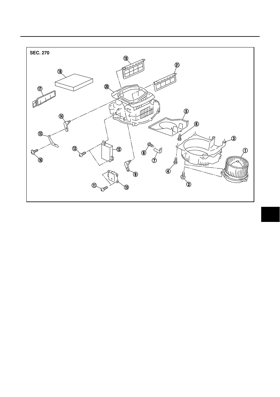
Disassembly and Assembly

NJS00096

1.

Blower motor assembly

2.

Screw

3.

Lower case

4.

Screw

5.

Bell mouth

6.

Screw

7.

Clamp

8.

Screw

9.

Intake door lever No. 1

10.

Intake door motor

11.

Screw

12.

Auto amp.

13.

Screw

14. Intake door lever No. 2

15.

Intake door link

16.

Screw

17. Filter cover

18.

In-cabin microfilter

19.

Intake door No. 2

20. Upper case

21.

Intake door No. 1

RJIA0315E

ATC-132

BLOWER MOTOR

BLOWER MOTOR

PFP:27226

Removal and Installation

NJS00097

REMOVAL

1.

Remove glove box cover and instrument lower cover. Refer to 

IP-10, "Removal and Installation"

 .

2.

Disconnect blower motor connector.

3.

Remove mounting screws, and then remove blower motor.

INSTALLATION

Installation is basically the reverse order of removal.

SJIA0280E

INTAKE DOOR MOTOR

ATC-133

C

D

E

F

G

H

I

K

L

M

A

B

ATC

INTAKE DOOR MOTOR

PFP:27730

Removal and Installation

NJS00098

REMOVAL

1.

Remove instrument lower cover and instrument panel bracket. Refer to 

IP-10, "Removal and Installation"

 .

2.

Remove ECM with bracket attached.

3.

Disconnect intake door motor connector.

4.

Remove mounting screws, and then remove intake door motor
from blower unit.

INSTALLATION

Installation is basically the reverse order of removal.

RJIA0280E

ATC-134

IN-CABIN MICROFILTER

IN-CABIN MICROFILTER

PFP:27277

Removal and Installation

NJS00099

FUNCTION

Air inside passenger compartment is kept clean at either recircula-
tion or fresh mode by installing in-cabin microfilter into blower unit.

REPLACEMENT TIMING

Replace in-cabin microfilter.
Refer to 

MA-7, "CHASSIS AND BODY MAINTENANCE"

  in Schedule 1 and 

MA-9, "CHASSIS AND BODY

MAINTENANCE"

  in Schedule 2.

Caution label is fixed inside glove box.

REPLACEMENT PROCEDURES

1.

Remove glove box assembly. Refer to 

IP-10, "Removal and Installation"

 .

2.

Remove center cover of glove box cover. 

3.

Remove filter cover.

4.

Take out in-cabin microfilter from blower unit.

5.

Replace with new one and reinstall on blower unit.

6.

Reinstall glove box assembly.

RJIA1331E

RJIA1930E

RJIA1332E


Content   ..  132  133  134  135   ..