Infiniti Q45. Manual - part 66
CLOSED THROTTLE POSITION AND WIDE OPEN THROTTLE POSITION CIR-
CUIT
AT-177
D
E
F
G
H
I
J
K
L
M
A
B
AT
CLOSED THROTTLE POSITION AND WIDE OPEN THROTTLE POSITION CIR-
CUIT
PFP:18002
CONSULT-II Reference Value
NCS00106
Diagnostic Procedure
NCS00107
1.
CHECK CAN COMMUNICATION LINE
Perform the self-diagnosis. Refer to
AT-87, "SELF-DIAGNOSTIC RESULT MODE"
Is a malfunction in the CAN communication indicated in the results?
YES
>> Check CAN communication line. Refer to
AT-99, "DTC U1000 CAN COMMUNICATION LINE"
.
NO
>> GO TO 2.
2.
CHECK THROTTLE POSITION SIGNAL CIRCUIT
With CONSULT-II
1.
Turn ignition switch ON. (Do not start engine.)
2.
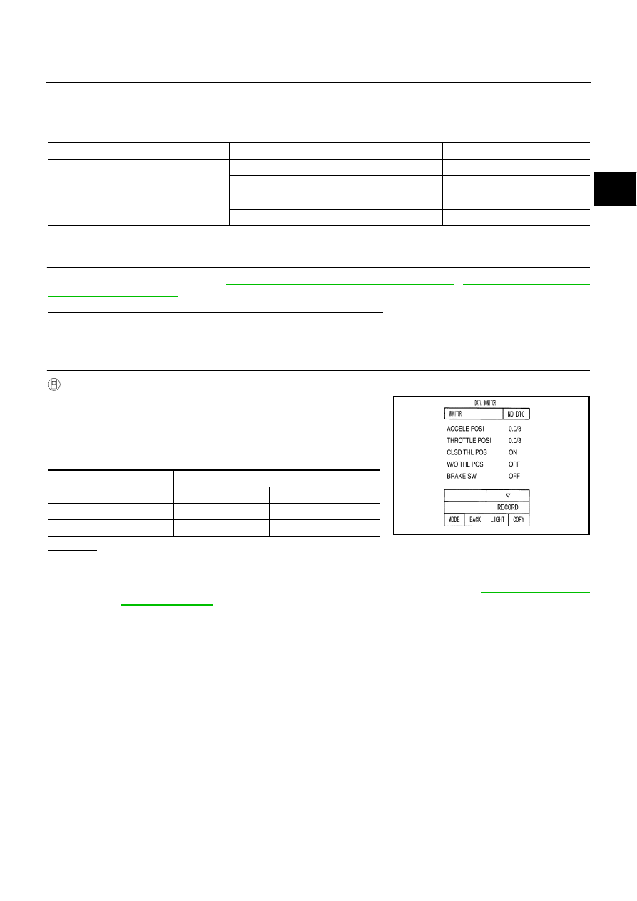
Select “ECU INPUT SIGNALS” in “DATA MONITOR” mode for
“A/T” with CONSULT-II.
3.
Depress accelerator pedal and read out the value of “CLSD THL
POS” and “W/O THL POS”.
OK or NG
OK
>> INSPECTION END
NG
>> Check the following. If NG, repair or replace damaged parts.
●
Perform the self-diagnosis for “ENGINE” with CONSULT-II. Refer to
.
●
Open circuit or short to ground or short to power in harness or connectors.
●
Pin terminals for damage or loose connection with harness connector.
Item name
Condition
Display value
CLSD THL POS
Released accelerator pedal.
ON
Fully depressed accelerator pedal.
OFF
W/O THL POS
Fully depressed accelerator pedal.
ON
Released accelerator pedal.
OFF
Accelerator Pedal Operation
Monitor Item
CLSD THL POS
W/O THL POS
Released
ON
OFF
Fully depressed
OFF
ON
PCIA0070E