Infiniti Q45. Manual - part 53


  Index      Infiniti     Infiniti Q45 - service repair manual 2006 year


Search            copyright infringement  


Content   ..  51  52  53  54   ..


Infiniti Q45. Manual - part 53


DTC P0745 LINE PRESSURE SOLENOID VALVE

AT-125

D

E

F

G

H

I

J

K

L

M

A

B

AT

Diagnostic Procedure

NCS000W7

1. 

CHECK INPUT SIGNAL

 With CONSULT-II

1.

Turn ignition switch ON. (Do not start engine.)

2.

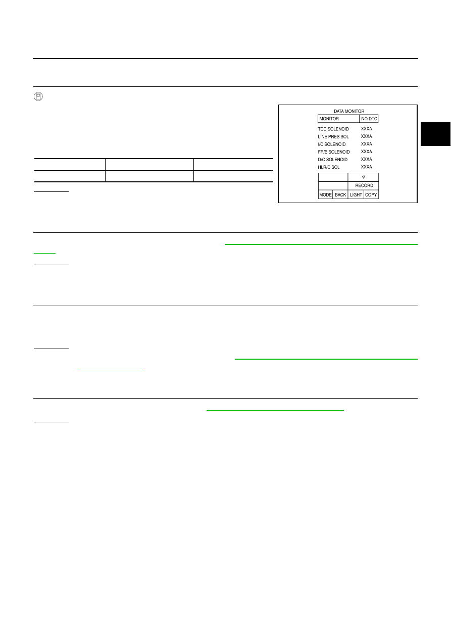
Select “MAIN SIGNALS” in “DATA MONITOR” mode for “A/T”
with CONSULT-II.

3.

Start engine.

4.

Read out the value of “LINE PRES SOL” during driving.

OK or NG

OK

>> GO TO 4.

NG

>> GO TO 2.

2. 

CHECK TCM POWER SUPPLY AND GROUND CIRCUIT

Check TCM power supply and ground circuit. Refer to 

AT-173, "MAIN POWER SUPPLY AND GROUND CIR-

CUIT"

 .

OK or NG

OK

>> GO TO 3.

NG

>> Repair or replace damaged parts.

3. 

DETECT MALFUNCTIONING ITEM

Check the following.

The A/T assembly harness connector pin terminals for damage or loose connection with harness connec-
tor.

OK or NG

OK

>> Replace the control valve with TCM. Refer to 

AT-225, "Control Valve with TCM and A/T Fluid Tem-

perature Sensor 2"

 .

NG

>> Repair or replace damaged parts.

4. 

CHECK DTC

Perform “DTC Confirmation Procedure”. Refer to 

AT-124, "DTC Confirmation Procedure"

 .

OK or NG

OK

>> INSPECTION END

NG

>> GO TO 2.

Item name

Condition 

Display value (Approx.) 

LINE PRES SOL

During driving

0.2 - 0.6 A

SCIA4793E

AT-126

DTC P1705 THROTTLE POSITION SENSOR

DTC P1705 THROTTLE POSITION SENSOR

PFP:22620

Description

NCS000WI

Electric throttle control actuator consists of throttle control motor, accelerator pedal position sensor, throttle
position sensor, etc. The actuator sends a signal to the ECM, and ECM sends signals to TCM with CAN com-
munication.

CONSULT-II Reference Value

NCS000WJ

On Board Diagnosis Logic

NCS000WK

This is not an OBD-II self-diagnostic item.

Diagnostic trouble code “P1705 TP SEN/CIRC A/T” with CONSULT-II or 15th judgement flicker without
CONSULT-II is detected when TCM does not receive the proper accelerator pedal position signals (input
by CAN communication) from ECM.

Possible Cause

NCS000WL

Harness or connectors
(Sensor circuit is open or shorted.)

DTC Confirmation Procedure

NCS000WM

NOTE:
If “DTC Confirmation Procedure” has been previously performed, always turn ignition switch OFF and
wait at least 10 seconds before performing the next test.
After the repair, perform the following procedure to confirm the malfunction is eliminated.

 WITH CONSULT-II

1.

Turn ignition switch ON. (Do not start engine.)

2.

Select “ECU INPUT SIGNALS” in “DATA MONITOR” mode for
“A/T” with CONSULT-II.

3.

Touch “START”.

4.

Start engine and let it idle for 1 second.

5.

If DTC is detected, go to 

AT-127, "Diagnostic Procedure"

 .

 WITH GST

Follow the procedure “WITH CONSULT-II”.

Item name

Condition

Display value (Approx.)

ACCELE POSI

Released accelerator pedal.

0.0/8

Fully depressed accelerator pedal.

8.0/8

BCIA0031E

DTC P1705 THROTTLE POSITION SENSOR

AT-127

D

E

F

G

H

I

J

K

L

M

A

B

AT

Diagnostic Procedure

NCS000WN

1. 

CHECK CAN COMMUNICATION LINE

Perform the self-diagnosis. Refer to 

AT-87, "SELF-DIAGNOSTIC RESULT MODE"

 , 

AT-97, "Diagnostic Proce-

dure without CONSULT-II"

 .

Is a malfunction in the CAN communication indicated in the results?

YES

>> Check CAN communication line. Refer to 

AT-99, "DTC U1000 CAN COMMUNICATION LINE"

 .

NO

>> GO TO 2.

2. 

CHECK DTC WITH TCM 

 With CONSULT-II

1.

Turn ignition switch ON. (Do not start engine.)

2.

Select “ECU INPUT SIGNALS” in “DATA MONITOR” mode for
“A/T” with CONSULT-II.

3.

Depress accelerator pedal and read out the value of “ACCELE
POSI”.

4.

Select “SELF-DIAG RESULTS” mode for “A/T” with CONSULT-
II. Refer to 

AT-87, "SELF-DIAGNOSTIC RESULT MODE"


OK or NG

OK

>> GO TO 4.

NG

>> GO TO 3.

3. 

CHECK DTC WITH ECM 

 With CONSULT-II

1.

Turn ignition switch ON. (Do not start engine.)

2.

Select “SELF-DIAG RESULTS” mode for “ENGINE” with CON-
SULT-II. Refer to 

EC-115, "CONSULT-II Function (ENGINE)"

 .

OK or NG

OK

>> GO TO 4.

NG

>> Check the DTC detected item. Refer to 

EC-115, "CON-

SULT-II Function (ENGINE)"

 .

If CAN communication line is detected, go to 

AT-99,

"DTC U1000 CAN COMMUNICATION LINE"

 .

4. 

CHECK DTC

Perform “DTC Confirmation Procedure”. Refer to 

AT-126, "DTC Confirmation Procedure"

 .

OK or NG

OK

>> INSPECTION END

NG

>> GO TO 5.

5. 

CHECK TCM POWER SUPPLY AND GROUND CIRCUIT

Check TCM power supply and ground circuit. Refer to 

AT-173, "MAIN POWER SUPPLY AND GROUND CIR-

CUIT"

 .

OK or NG

OK

>> GO TO 6.

NG

>> Repair or replace damaged parts.

Item name

Condition

Display value 
(Approx.)

ACCELE POSI

Released accelerator pedal.

0.0/8

Fully depressed accelerator pedal.

8.0/8

PCIA0070E

BCIA0030E

AT-128

DTC P1705 THROTTLE POSITION SENSOR

6. 

DETECT MALFUNCTIONING ITEM

Check the following.

The A/T assembly harness connector pin terminals for damage or loose connection with harness connec-
tor.

OK or NG

OK

>> Replace the control valve with TCM. Refer to 

AT-225, "Control Valve with TCM and A/T Fluid Tem-

perature Sensor 2"

 .

NG

>> Repair or replace damaged parts.


Content   ..  51  52  53  54   ..