Infiniti Q45. Manual - part 47


  Index      Infiniti     Infiniti Q45 - service repair manual 2006 year


Search            copyright infringement  


Content   ..  45  46  47  48   ..


Infiniti Q45. Manual - part 47


DTC U1000 CAN COMMUNICATION LINE

AT-101

D

E

F

G

H

I

J

K

L

M

A

B

AT

TCM terminals and data are reference value. Measured between each terminal and ground.

Diagnostic Procedure

NCS000UT

1. 

CHECK CAN COMMUNICATION CIRCUIT

 With CONSULT-II

1.

Turn ignition switch ON and start engine.

2.

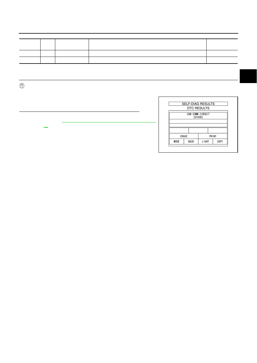
Select “SELF-DIAG RESULTS” mode for “A/T” with CONSULT-
II.

Is any malfunction of the “CAN COMM CIRCUIT” indicated?

YES

>> Print out CONSULT-II screen, GO TO LAN section.

Refer to 

LAN-17, "Precautions When Using CONSULT-

II"

 .

NO

>> INSPECTION END

Terminal

Wire 

color

Item

Condition

Data (Approx.)

3

L

CAN-H

8

P

CAN-L

PCIA0061E

AT-102

DTC P0615 START SIGNAL CIRCUIT

DTC P0615 START SIGNAL CIRCUIT

PFP:25230

Description

NCS000UU

TCM prohibits cranking other than at “P” or “N” position.

CONSULT-II Reference Value

NCS000UV

On Board Diagnosis Logic

NCS000UW

This is not an OBD-II self-diagnostic item. 

Diagnostic trouble code “P0615 STARTER RELAY/CIRC” with CONSULT-II or 14th judgement flicker
without CONSULT-II is detected when starter relay is switched ON other than at “P” or “N” position. (Or
when switched OFF at “P” or “N” position).

Possible Cause

NCS000UX

Harness or connectors
(Park/neutral position relay and TCM circuit is open or shorted.)

Park/neutral position relay circuit

DTC Confirmation Procedure

NCS000UY

NOTE:
If “DTC Confirmation Procedure” has been previously performed, always turn ignition switch OFF and
wait at least 10 seconds before performing the next test.
After the repair, perform the following procedure to confirm the malfunction is eliminated.

 WITH CONSULT-II

1.

Turn ignition switch ON. (Do not start engine.)

2.

Select “SELECTION FROM MENU” in “DATA MONITOR” mode
for “A/T” with CONSULT-II and check monitor “STARTER
RELAY” ON/OFF.

3.

Touch “START”.

4.

Start engine.

5.

Drive vehicle for at least 2 consecutive seconds.

6.

If DTC is detected, go to 

AT-104, "Diagnostic Procedure"

 .

Item name

Condition 

Display value

STARTER RELAY

Selector lever in “N”, “P” positions.

ON

Selector lever in other positions.

OFF

BCIA0031E

DTC P0615 START SIGNAL CIRCUIT

AT-103

D

E

F

G

H

I

J

K

L

M

A

B

AT

Wiring Diagram — AT — STSIG

NCS000UZ

TCWM0302E

AT-104

DTC P0615 START SIGNAL CIRCUIT

TCM terminals and data are reference value. Measured between each terminal and ground.

Diagnostic Procedure

NCS000V0

1. 

CHECK STARTER RELAY

 With CONSULT-II

1.

Turn ignition switch ON. (Do not start engine.)

2.

Select “SELECTION FROM MENU” in “DATA MONITOR” mode
for “A/T” with CONSULT-II and check monitor “STARTER
RELAY” ON/OFF.

OK or NG

OK

>> GO TO 6.

NG

>> GO TO 2.

2. 

 CHECK HARNESS BETWEEN A/T ASSEMBLY HARNESS CONNECTOR AND PARK/NEUTRAL 

POSITION RELAY HARNESS CONNECTOR

1.

Turn ignition switch OFF.

2.

Remove park/neutral position relay.

3.

Disconnect A/T assembly harness connector.

4.

Check continuity between A/T assembly harness connector ter-
minal and park/neutral position relay harness connector termi-
nal.

5.

If OK, check harness for short to ground and short to power.

OK or NG

OK

>> GO TO 3.

NG

>> Repair open circuit or short to ground or short to power in harness or connectors.

3. 

 CHECK PARK/NEUTRAL POSITION RELAY GROUND CIRCUIT

1.

Check continuity between park/neutral position relay harness
connector terminal and ground.

2.

If OK, check harness for short to ground and short to power.

3.

Reinstall any part removed.

OK or NG

OK

>> GO TO 4.

NG

>> Repair open circuit or short to ground or short to power

in harness or connectors.

Terminal

Wire 

color

Item

Condition

Data (Approx.)

9

B/W

Park/neutral posi-
tion relay

Selector lever in “N”, “P” positions.

Battery voltage

Selector lever in other positions.

0 V

Item name

Condition 

Display value

STARTER RELAY

Selector lever in “N”, “P” positions.

ON

Selector lever in other positions.

OFF

PCIA0056E

Item

 Connector

Terminal

Continuity

A/T assembly harness con-
nector

F26

9

Yes

Park/neutral position relay 
harness connector

E3-6

1

SCIA5847E

Continuity should exist.

SCIA5848E


Content   ..  45  46  47  48   ..