Infiniti Q45. Manual - part 21
ELECTRICAL COMPONENT INSPECTION
ACS-77
[ICC]
C
D
E
F
G
H
I
J
L
M
A
B
ACS
ELECTRICAL COMPONENT INSPECTION
PFP:00000
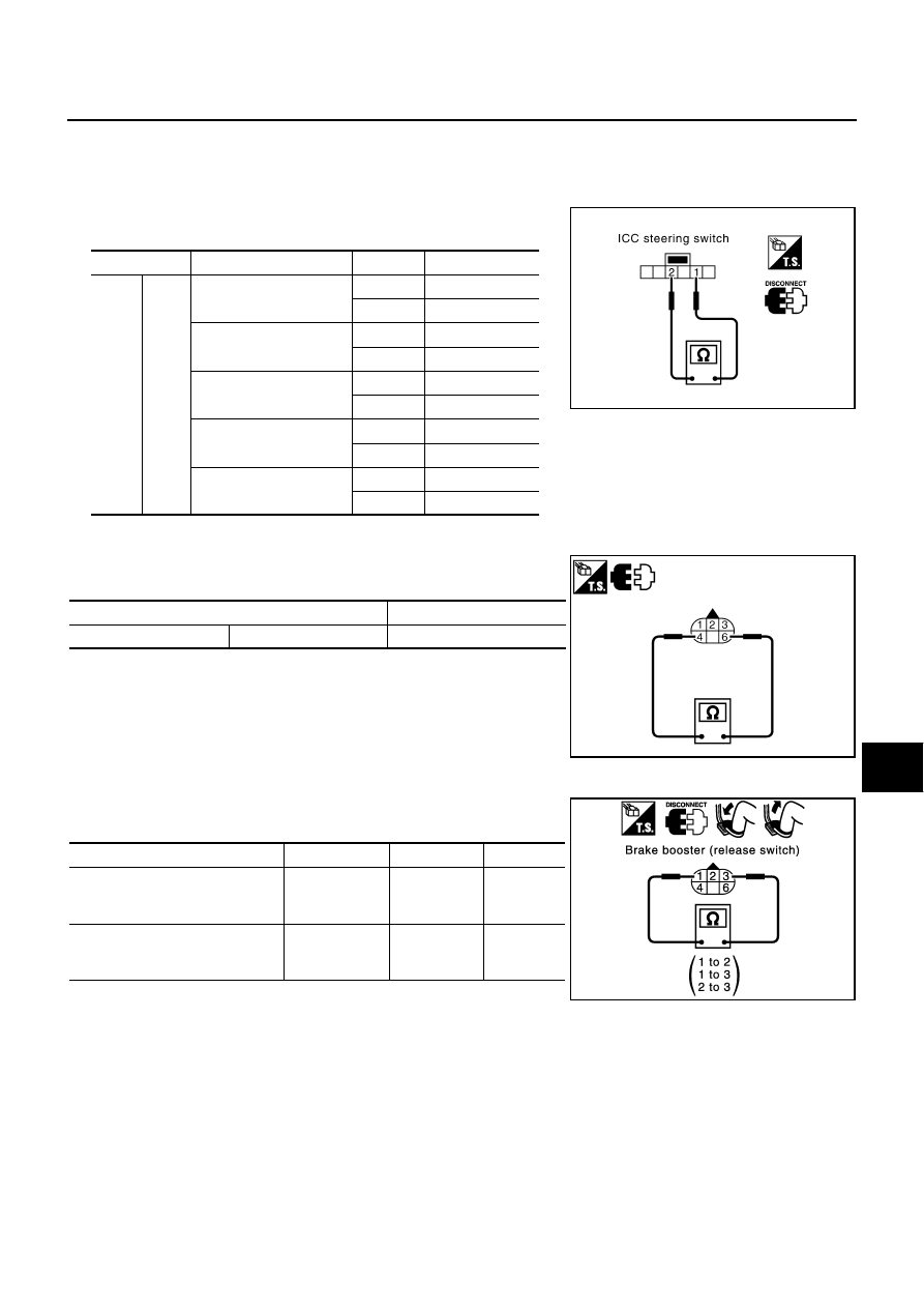
ICC Steering Switch
NKS001LB
1.
Remove ICC steering switch.
2.
Check resistance between ICC steering switch terminals by
pressing each switch.
Booster Solenoid
NKS001LD
Disconnect brake booster connector, and check resistance between
terminals.
Release Switch
NKS001LE
Disconnect brake booster connector and check resistance between
terminals.
(Note): However, if pedal is depressed insufficiently, resistance value may remain
unchanged.
Terminals
Switch
Condition
Resistance [k
Ω
]
1
2
MAIN
Pressed
Approx. 0
Released
Approx. 5.5
DISTANCE
Pressed
Approx. 0.7
Released
Approx. 5.5
RESUME/ACCELERATE
Pressed
Approx. 2.6
Released
Approx. 5.5
SET/COAST
Pressed
Approx. 1.4
Released
Approx. 5.5
CANCEL
Pressed
Approx. 0.3
Released
Approx. 5.5
PKIA2215E
Terminals
Resistance [
Ω
]
4
6
Approx. 1.4
PKIC5181E
Condition
1 - 3
1 - 2
2 - 3
Release the brake pedal.
Continuity
should exist.
Continuity
should not
exist.
Continuity
should not
exist.
Depress the brake pedal.
Continuity
should not
exist. (Note)
Continuity
should exist.
(Note)
Continuity
should not
exist.
SKIA1256E