Infiniti Q45. Manual - part 10
TROUBLE DIAGNOSIS - GENERAL DESCRIPTION
ACS-33
[ICC]
C
D
E
F
G
H
I
J
L
M
A
B
ACS
CONSULT-II Function (ICC)
NKS001KC
CONSULT-II can display each diagnostic item using the diagnostic test modes shown following.
CONSULT-II BASIC OPERATION
Refer to
GI-36, "CONSULT-II Start Procedure"
.
WORK SUPPORT
Work Item
Cause of Auto-Cancel
1.
Touch “WORK SUPPORT” on the “SELECT DIAG MODE”
screen. Refer to
ACS-33, "CONSULT-II BASIC OPERATION"
.
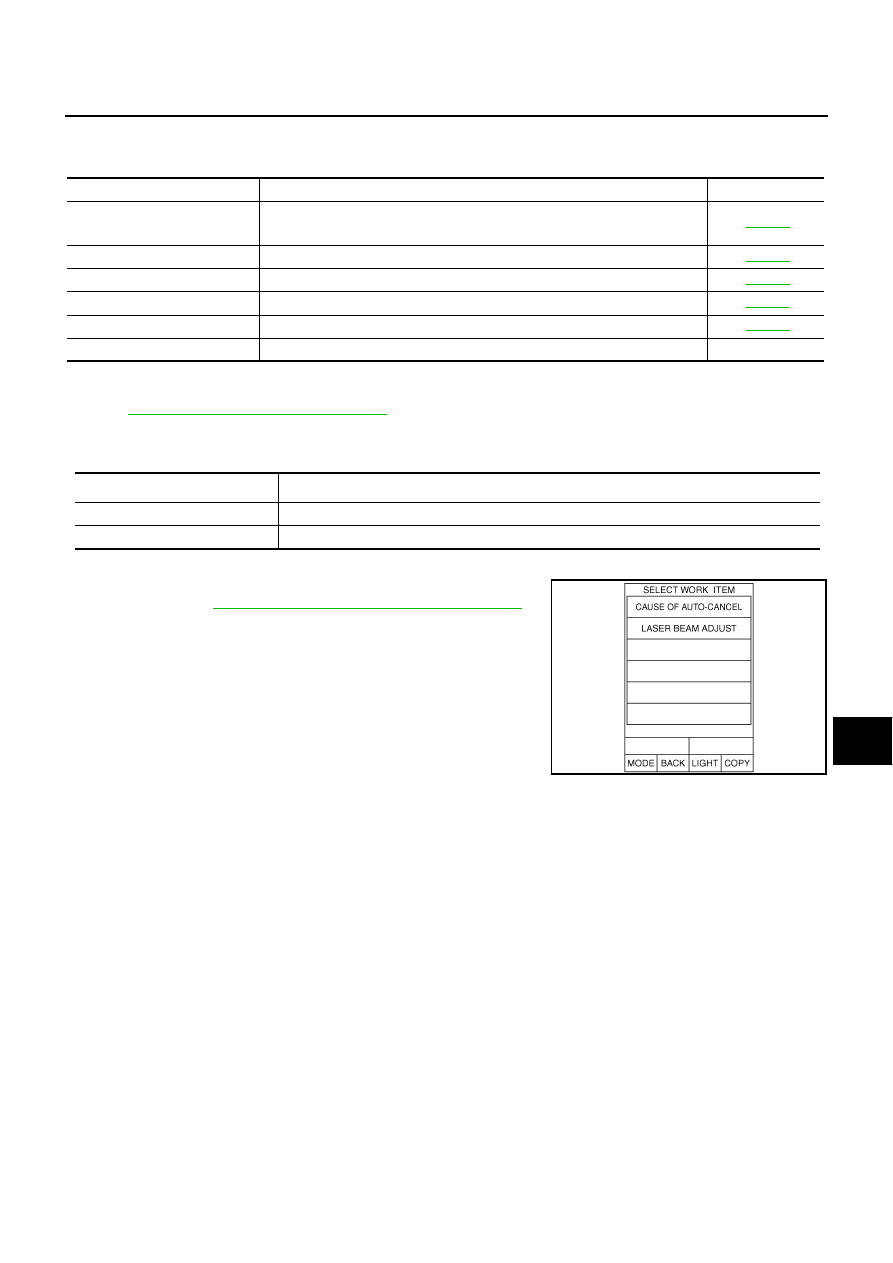
2.
Touch “CAUSE OF AUTO-CANCEL” on the “SELECT WORK
ITEM” screen.
3.
Cause of automatic cancellation screen will be shown.
NOTE:
Last five cancels (system cancel) causes are displayed.
Test mode
Function
Reference page
WORK SUPPORT
●
Monitors aiming direction to facilitate laser beam aiming operation.
●
Indicates causes of automatic cancellation of the ICC system.
SELF-DIAG RESULTS
Displays malfunctioning system memorized in ICC unit.
DATA MONITOR
Displays real-time input/output data of ICC unit.
CAN DIAG SUPPORT MNTR
The results of transmit/receive diagnosis of CAN communication can be read.
ACTIVE TEST
Enables operation check of electrical loads by sending driving signal to them.
ECU PART NUMBER
Displays part number of ICC unit.
—
Operation
Function
CAUSE OF AUTO-CANCEL
Indicates causes of automatic cancellation of the ICC system.
LASER BEAM ADJUST
Outputs laser beam, calculates dislocation of the beam, and indicates adjustment direction.
SKIA6191E