Infiniti Q45 (FY33). Manual - part 533


  Index      Infiniti     Infiniti Q45 (FY33) - service repair manual 2001 year


Search            copyright infringement  


Content   ..  531  532  533  534   ..


Infiniti Q45 (FY33). Manual - part 533


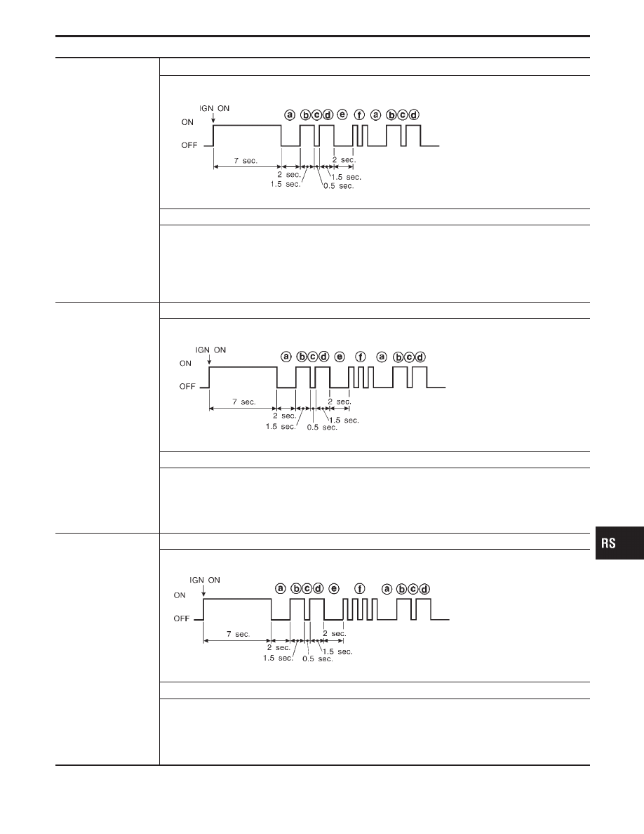
The side air bag module
(LH) circuit is out of
order.
(

q

f

: 2 flashes)

Flash pattern

SRS337

q

a

through

q

f

are repeated.

q

f

— Two flashes indicate

malfunctioning side air
bag module (LH) circuit.

Repair order (“Recheck SRS at each replacement.”)

1. Visually check the wiring harness connection.
2. Replace the harness if it has visible damage.
3. Replace side air bag module (LH).

(Before disposal, it must be deployed.)

4. Replace the diagnosis sensor unit.
5. Replace the related harness.

The satellite sensor
(RH) is out of order.
(

q

f

: 3 flashes)

Flash pattern

SRS340

q

a

through

q

f

are repeated.

q

f

— Three flashes indicate

malfunctioning satellite
sensor (RH) circuit.

Repair order (“Recheck SRS at each replacement.”)

1. Visually check the wiring harness connection.
2. Replace the harness if it has visible damage.
3. Replace the satellite sensor (RH).
4. Replace the diagnosis sensor unit.
5. Replace the related harness.

The satellite sensor
(LH) is out of order.
(

q

f

: 4 flashes)

Flash pattern

SRS339-A

q

a

through

q

f

are repeated.

q

f

— Four flashes indicate

malfunctioning satellite
sensor (LH) circuit.

Repair order (“Recheck SRS at each replacement.”)

1. Visually check the wiring harness connection.
2. Replace the harness if it has visible damage.
3. Replace the satellite sensor (LH).
4. Replace the diagnosis sensor unit.
5. Replace the related harness.

* Follow the procedures in numerical order when repairing malfunctioning parts. Confirm whether malfunction is eliminated

using the air bag warning lamp (in User mode) or CONSULT-II each time repair is finished. If malfunction is still observed,
proceed to the next step. When malfunction is eliminated, further repair work is not required.

GI

MA

EM

LC

EC

FE

AT

PD

FA

RA

BR

ST

BT

HA

EL

IDX

TROUBLE DIAGNOSES — Supplemental Restraint System (SRS)

Self-diagnosis (Cont’d)

RS-47

SEF046TA

DIAGNOSTIC PROCEDURE 4 (

with CONSULT-II)

Final checking after repairing SRS by using CONSULT-II —
Diagnosis mode
1.

After repairing SRS, connect both battery cables.

2.

Connect CONSULT-II to Data link connector.

3.

Turn ignition switch from “OFF” to “ON”.

SRS695

4.

Touch “START”.

SRS771

5.

Touch “AIR BAG”.

SRS697

6.

Touch “SELF-DIAG [CURRENT]”.

SRS701

7.

If no malfunction is detected on “SELF-DIAG [CURRENT]”,
repair of SRS is completed. Go to step 8.
(When the malfunction was only in seat belt pre-tensioner
system, go to step 11.)
If any malfunction is detected on “SELF-DIAG [CURRENT]”,
the malfunctioning part is not repaired completely or another
malfunctioning part is detected. Go to DIAGNOSTIC PROCE-
DURE 2, page RS-40, and repair malfunctioning part com-
pletely.

TROUBLE DIAGNOSES — Supplemental Restraint System (SRS)

Self-diagnosis (Cont’d)

RS-48

SRS773

8.

Touch “ERASE”.

NOTE:
Touch “ERASE” to clear the memory of the malfunction
(“SELF-DIAG [PAST]”).

If the memory of the malfunction is “SELF-DIAG [PAST]” is not
erased, the User mode shows the system malfunction by the
operation of the warning lamp even if the malfunction is
repaired completely.

SRS771

9.

Touch “BACK” key of CONSULT-II to select “SELF-DIAG
[PAST]” in the “SELECT DIAG MODE” screen. Touch “SELF-
DIAG [PAST]”.

SRS702

10. Check that no malfunction is detected on “SELF-DIAG

[PAST]”.

NOTE:
Past malfunction for seat belt pre-tensioner system will not be
displayed on “SELF-DIAG [PAST]”.

11. Touch “BACK” key of CONSULT-II until SELECT SYSTEM

appears in order to return to User mode from Diagnosis mode.

12. Turn ignition switch “OFF” then turn off and disconnect CON-

SULT-II.

13. Go to DIAGNOSTIC PROCEDURE 1, page RS-38 to check

SRS operation by using “AIR BAG” warning lamp with User
mode.

GI

MA

EM

LC

EC

FE

AT

PD

FA

RA

BR

ST

BT

HA

EL

IDX

TROUBLE DIAGNOSES — Supplemental Restraint System (SRS)

Self-diagnosis (Cont’d)

RS-49

SRS247

DIAGNOSTIC PROCEDURE 5 (

without CONSULT-

II)

Final checking after repairing SRS by using “AIR BAG” warn-
ing lamp — Diagnosis mode and User mode
1.

After repairing SRS connect both battery cables.

2.

Open driver’s door.

3.

Turn ignition switch from “OFF” to “ON”.

4.

“AIR BAG” warning lamp operates in Diagnosis mode as fol-
lows:

No.

“AIR BAG” warning lamp flash pattern — Diagnosis mode —

SRS condition

1

SRS333

q

a

through

q

b

are repeated.

No malfunc-
tion is
detected or
repair is com-
pleted.
No further
action is nec-
essary.

2

SRS341

q

a

through

q

d

are repeated.

q

b

— Driver and passenger air

bag marker (For identifying
driver and/or passenger air
bag malfunctioning)

q

d

— Indicates malfunctioning

part. The number of flashes
varies with malfunctioning
part (0.5 sec. ON and 0.5
sec. OFF is counted as one
flash.)

The system is
malfunctioning
and needs to
be repaired.

3

SRS342-A

q

a

through

q

f

are repeated.

q

b

,

q

c

,

q

d

— Side air bag marker

(For identifying side
air bag malfunction-
ing)

q

f

— Indicates malfunctioning

part. The number of flashes
varies with malfunctioning
part (0.5 sec. ON and 0.5
sec. OFF is counted as one
flash.)

NOTE:
When diagnosis sensor unit is replaced with new one, “AIR
BAG” warning lamp will operate in User mode. Checking “AIR
BAG” warning lamp operation in Diagnosis mode is not
required. Go to step 6.

TROUBLE DIAGNOSES — Supplemental Restraint System (SRS)

Self-diagnosis (Cont’d)

RS-50


Content   ..  531  532  533  534   ..