Infiniti Q45 (FY33). Manual - part 512
SPD526
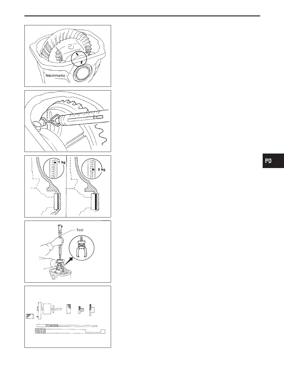
5.
Install the side bearing caps in their correct locations and
torque the bearing cap retaining bolts.
Specification:
88 - 98 N
⋅
m (9 - 10 kg-m, 65 - 72 ft-lb)
6.
Turn the carrier several times to seat the bearings.
SPD194A
7.
Measure the turning torque of the carrier at the ring gear retain-
ing bolts with a spring gauge, J-8129.
Specification:
34.3 - 39.2 N (3.5 - 4 kg, 7.7 - 8.8 lb)
of pulling force at the ring gear bolt
SPD772
8.
If the turning torque is not within the specifications correct the
torque as follows:
I
If the turning torque is less than the specified range, install
washers of greater thickness.
I
If the turning torque is greater than the specification, install
thinner washers.
I
See the SDS section for washer dimensions and part numbers.
9.
Record the total amount of washer thickness required for the
correct carrier side bearing preload.
PD344
10. Remove the carrier from the final drive housing. Save the
selected preload washers for later use during the assembly of
the final drive unit.
Tool number: HT72400000 (
—
)
SPD769
Pinion Gear Height and Pinion Bearing Preload
1.
Make sure all parts are clean and that the bearings are well
lubricated.
2.
Assemble the pinion gear bearings into the pinion preload shim
selector Tool, J-34309.
GI
MA
EM
LC
EC
FE
AT
FA
RA
BR
ST
RS
BT
HA
EL
IDX
ADJUSTMENT
Side Bearing Preload (Cont’d)
PD-21