Infiniti Q45 (FY33). Manual - part 492


  Index      Infiniti     Infiniti Q45 (FY33) - service repair manual 2001 year


Search            copyright infringement  


Content   ..  490  491  492  493   ..


Infiniti Q45 (FY33). Manual - part 492


I

Cooling unit (Evaporator)
With engine “off”, turn blower fan on “High” for at least 15 sec-
onds to dissipate any refrigerant trace in the cooling unit. Wait
a minimum of ten minutes accumulation time* before inserting
the leak detector probe into the drain hose. (Keep the probe
inserted for at least ten seconds.) Use caution not to contami-
nate the probe tip with water or dirt that may be in the drain
hose.
*: (Refer to the manufacturer’s recommended procedure for

actual wait time.)

5.

If a leak detector detects a leak, verify at least once by blow-
ing compressed air into area of suspected leak, then repeat
check as outlined above.

6.

Do not stop when one leak is found. Continue to check for
additional leaks at all system components. If no leaks are
found, perform steps 7 - 10.

7.

Start engine.

8.

Set the heater A/C control as follows:

a.

A/C switch ON

b.

Face mode

c.

Recirculation switch ON

d.

Max cold temperature

e.

Fan speed high

9.

Run engine at 1,500 rpm for at least 2 minutes.

10. Turn engine off and perform leak check again, following steps

4 through 6 above.

SHA839E

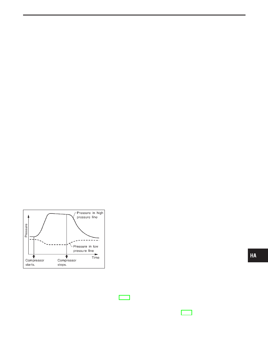
Refrigerant leaks should be checked immediately after stop-
ping the engine. Begin with the leak detector at the compres-
sor. The pressure on the high pressure side will gradually
drop after refrigerant circulation stops and pressure on the
low pressure side will gradually rise, as shown in the graph.
Some leaks are more easily detected when pressure is high.

11. Before connecting ACR4 to vehicle, check ACR4 gauges. No

refrigerant pressure should be displayed. If NG, recover refrig-
erant from equipment lines.

12. Confirm refrigerant purity in supply tank using ACR4 and refrig-

erant identifier. If NG, refer to “Contaminated refrigerant”,
HA-3.

13. Connect ACR4 to vehicle. Confirm refrigerant purity in vehicle

A/C system using ACR4 and refrigerant identifier. If NG, refer
to “Contaminated refrigerant”, HA-3.

14. Discharge A/C system using approved refrigerant recovery

equipment. Repair the leaking fitting or component as neces-
sary.

GI

MA

EM

LC

EC

FE

AT

PD

FA

RA

BR

ST

RS

BT

EL

IDX

SERVICE PROCEDURES

Electronic Refrigerant Leak Detector (Cont’d)

HA-133

15. Evacuate and recharge A/C system and perform the leak test

to confirm no refrigerant leaks.

16. Conduct A/C performance test to ensure system works prop-

erly.

Fluorescent Dye Leak Detector

PRECAUTIONS FOR FLUORESCENT DYE LEAK
DETECTION

I

The fluorescent dye leak detector is not a replacement for an
electronic refrigerant leak detector. The fluorescent dye leak
detector should be used in conjunction with an electronic
refrigerant leak detector (J-41995) to pinpoint refrigerant leaks.

I

For your safety and your customer’s satisfaction, read and fol-
low all manufacturer’s operating instructions and precautions
prior to performing the work.

I

Refer to “Precautions for Leak Detection Dye”, HA-4.

CHECKING SYSTEM FOR LEAKS USING THE
FLUORESCENT LEAK DETECTOR

1.

Check A/C system for leaks using the UV lamp and safety
glasses (J-42220) in a low sunlight area (area without windows
preferable). Illuminate all components, fittings and lines. The
dye will appear as a bright green/yellow area at the point of
leakage. Fluorescent dye observed at the evaporator drain
opening indicates an evaporator core assembly (tubes, core or
TXV) leak.

2.

If the suspected area is difficult to see, use an adjustable mir-
ror or wipe the area with a clean shop rag or cloth, then check
the cloth with the UV lamp for dye residue.

3.

Confirm any suspected leaks with an approved electronic
refrigerant leak detector.

4.

After the leak is repaired, remove any residual dye using dye
cleaner (J-43872) to prevent future misdiagnosis.

5.

Perform a system performance check and verify the leak repair
with an approved electronic refrigerant leak detector.

DYE INJECTION

(This procedure is only necessary when re-charging the system or
when the compressor has seized and was replaced.)
Refer to “Precautions for Leak Detection Dye”, HA-4.
1.

Check A/C system static (at rest) pressure. Pressure must be
at least 345 kPa (3.52 kg/cm

2

, 50 psi).

2.

Pour one bottle (1/4 ounce / 7.4 cc) of the A/C refrigerant dye
into the injector tool (J-41459).

3.

Connect the injector tool to the A/C LOW PRESSURE side
service fitting.

4.

Start engine and switch A/C ON.

5.

With the A/C operating (compressor running), inject one bottle
(1/4 ounce / 7.4 cc) of fluorescent dye through the low-pres-
sure service valve using dye injector tool J-41459 (refer to the
manufacturer’s operating instructions).

6.

With the engine still running, disconnect the injector tool from
the service fitting.

CAUTION:

Be careful not to allow dye to spray or drip when disconnect-
ing the injector from the system.

SERVICE PROCEDURES

Electronic Refrigerant Leak Detector (Cont’d)

HA-134

NOTE:
If repairing the A/C system or replacing a component, pour the
dye directly into the open system connection and proceed
with the service procedures.
7.

Operate the A/C system for a minimum of 20 minutes to mix
the dye with the system oil. Depending on the leak size, oper-
ating conditions and location of the leak, it may take from min-
utes to days for the dye to penetrate a leak and become vis-
ible.

Compressor Mounting

RHA954F

Belt Tension

I

Refer to MA section.

Fast Idle Control Device (FICD)

I

Refer to EC section.

GI

MA

EM

LC

EC

FE

AT

PD

FA

RA

BR

ST

RS

BT

EL

IDX

SERVICE PROCEDURES

Fluorescent Dye Leak Detector (Cont’d)

HA-135

Compressor

RHA122F

RHA136EB

RHA399F

Compressor Clutch

REMOVAL

I

When removing center bolt, hold clutch disc with clutch disc
wrench.

SERVICE PROCEDURES

HA-136


Content   ..  490  491  492  493   ..