Infiniti Q45 (FY33). Manual - part 491


  Index      Infiniti     Infiniti Q45 (FY33) - service repair manual 2001 year


Search            copyright infringement  


Content   ..  489  490  491  492   ..


Infiniti Q45 (FY33). Manual - part 491


q

A

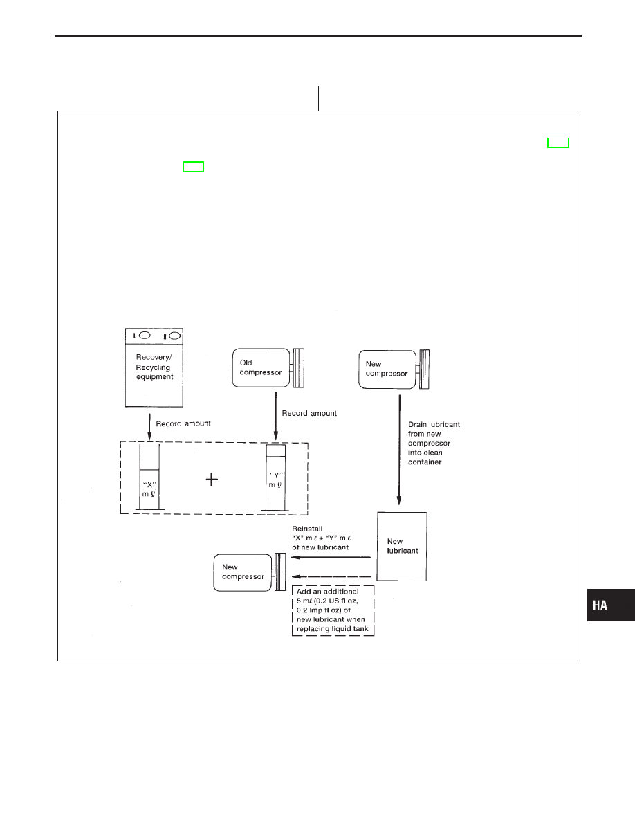
Lubricant adjusting procedure for COMPRESSOR REPLACEMENT
1. Check ACR4 gauges. No refrigerant pressure should be displayed. If NG, recover refrigerant from equipment lines.
2. Confirm refrigerant purity in supply tank using ACR4 and refrigerant identifier. If NG, refer to “Contaminated refrigerant”, HA-3.
3. Connect ACR4 to vehicle. Confirm refrigerant purity in vehicle A/C system using ACR4 and refrigerant identifier. If NG, refer to

“Contaminated refrigerant”, HA-3.

4. Discharge refrigerant into the refrigerant recovery/recycling equipment. Measure lubricant discharged into the recovery/

recycling equipment.

5. Drain the lubricant from the “old” (removed) compressor into a graduated container and record the amount of lubricant

drained.

6. Drain the lubricant from the “new” compressor into a separate, clean container
7. Measure an amount of new lubricant installed equal to amount drained from “old” compressor. Add this lubricant to “new”

compressor through the suction port opening.

8. Measure an amount of “new” lubricant equal to the amount recovered during discharging. Add this lubricant to “new” com-

pressor through the suction port opening.

9. If the liquid tank also needs to be replaced, add an additional 5 m


(0.2 US fl oz, 0.2 Imp fl oz) of lubricant at this time.

Do not add this 5 m


(0.2 US fl oz, 0.2 Imp fl oz) of lubricant if replacing only the compressor.

AHA374

GI

MA

EM

LC

EC

FE

AT

PD

FA

RA

BR

ST

RS

BT

EL

IDX

SERVICE PROCEDURES

Maintenance of Lubricant Quantity in
Compressor (Cont’d)

H

HA-129

Refrigerant Lines

I

Refer to page HA-5 regarding “Precautions for Refrigerant
Connection”.

RHA952FC

SERVICE PROCEDURES

HA-130

Checking Refrigerant Leaks

PRELIMINARY CHECK

I

Perform a visual inspection of all refrigeration parts, fittings,
hoses and components for signs of A/C lubricant leakage,
damage and corrosion. A/C lubricant leakage may indicate an
area of refrigerant leakage. Allow extra inspection time in these
areas when using either an electronic refrigerant leak detector
or fluorescent dye leak detector.

I

If dye is observed, confirm the leak with an approved electronic
refrigerant leak detector. It is possible a prior leak was repaired
and not properly cleaned.

I

When searching for leaks, do not stop when one leak is found
but continue to check for additional leaks at all system compo-
nents and connections.

I

When searching for refrigerant leaks using an electronic leak
detector, move the probe along the suspected leak area at 25
to 50 mm (1 to 2 in) per second an no further than 1/4 inch from
the component.

NOTE:
Moving the electronic leak detector probe slower and closer to
the suspected leak area will improve the chances of finding a
leak.

SHA196F

Electronic Refrigerant Leak Detector

PRECAUTIONS FOR HANDLING LEAK DETECTOR

When performing a refrigerant leak check, use a J-41995 electronic
refrigerant leak detector or equivalent. Ensure that the instrument
is calibrated and set properly per the operating instructions.
The leak detector is a delicate device. In order to use the leak
detector properly, read the operating instructions and perform any
specified maintenance.

I

Other gases in the work area or substances on the A/C
components, for example, anti-freeze, windshield washer
fluid, solvents and lubricants, may falsely trigger the leak
detector. Make sure the surfaces to be checked are clean.
Clean with a dry cloth or blow off with shop air.

I

Do not allow the sensor tip of the detector to contact with
any substance. This can also cause false readings and
may damage the detector.

SHA707EA

1.

Position probe approximately 5 mm (3/16 in) away from point
to be checked.

GI

MA

EM

LC

EC

FE

AT

PD

FA

RA

BR

ST

RS

BT

EL

IDX

SERVICE PROCEDURES

HA-131

SHA706E

2.

When testing, circle each fitting completely with probe.

SHA708EA

3.

Move probe along component approximately 25 to 50 mm (1
to 2 in)/sec.

CHECKING PROCEDURE

To prevent inaccurate or false readings, make sure there is no
refrigerant vapor, shop chemicals or smoke in the vicinity of
the vehicle. Perform the leak test in a calm area (low air/wind
movement) so that the leaking refrigerant is not dispersed.
1.

Turn engine off.

2.

Connect a suitable A/C manifold gauge set to the A/C service
ports.

3.

Check if the A/C refrigerant pressure is at least 345 kPa (3.52
kg/cm

2

, 50 psi) above 16°C (61°F). If less than specification,

recovery/evacuate and recharge the system with the specified
amount of refrigerant.
NOTE: At temperatures below 16°C (61°F), leaks may not be

detected since the system may not reach 345 kPa
(3.52 kg/cm

2

, 50 psi).

4.

Conduct the leak test from the high side (compressor dis-
charge

q

a

to evaporator inlet

q

g

) to the low side (drain hose

q

h

to shaft seal

q

m

). Refer to HA-130.

Perform a leak check for the following areas carefully. Clean
the component to be checked and move the leak detector
probe completely around the connection/component.

I

Compressor
Check the fitting of high and low pressure hoses, relief valve
and shaft seal.

I

Liquid tank
Check the pressure switch, tube fitting, weld seams and the
fusible plug mounts.

I

Service valves
Check all around the service valves. Ensure service valve caps
are secured on the service valves (to prevent leaks).
NOTE: After removing A/C manifold gauge set from service

valves, wipe any residue from valves to prevent any
false readings by leak detector.

SERVICE PROCEDURES

Electronic Refrigerant Leak Detector (Cont’d)

HA-132


Content   ..  489  490  491  492   ..