Infiniti Q45 (FY33). Manual - part 490
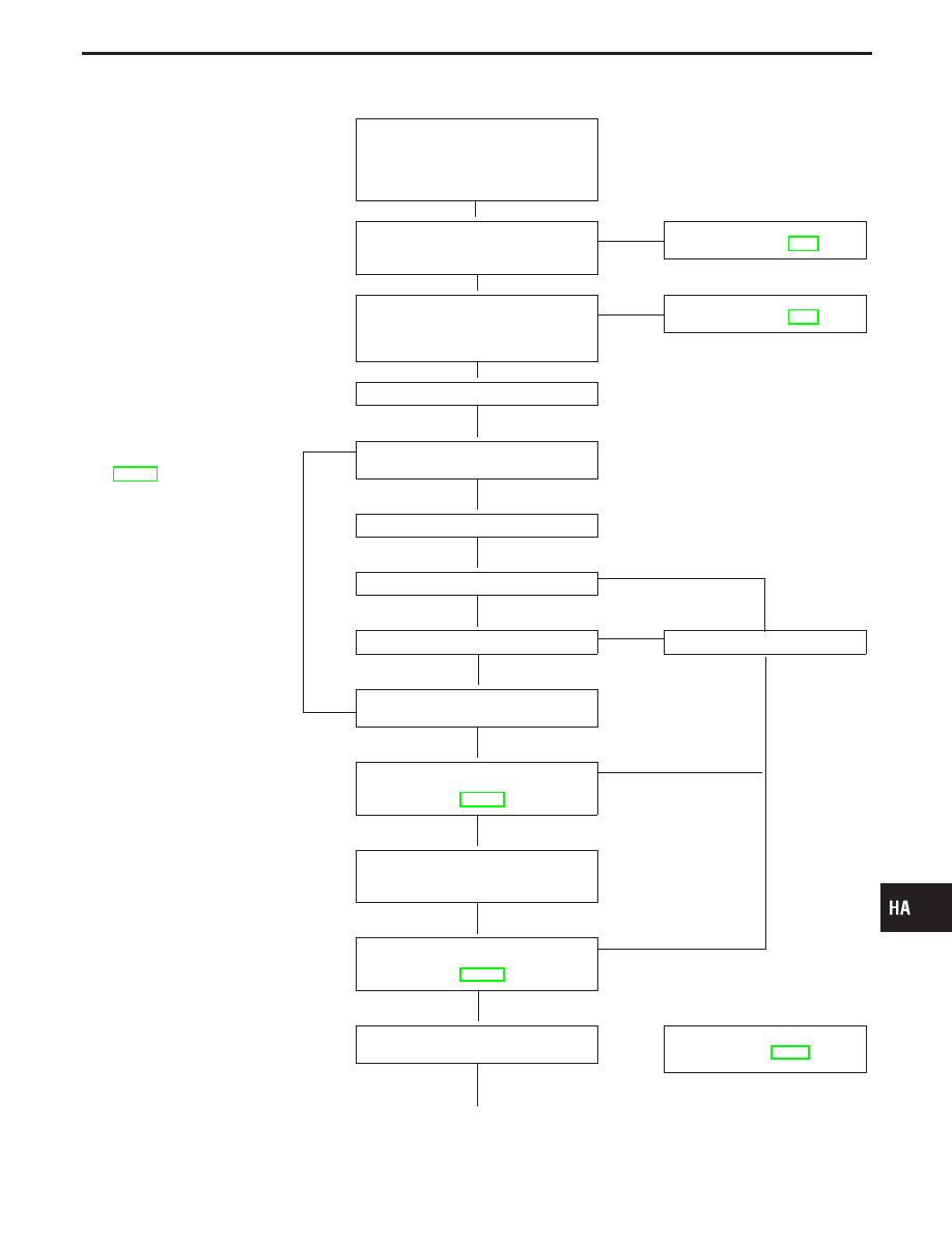
HFC-134a (R-134a) Service Procedure
Before connecting ACR4 to vehicle,
check ACR4 gauges. No refrigerant
pressure should be displayed.
If NG, recover refrigerant from equip-
ment lines.
Confirm refrigerant purity in supply
tank using ACR4 and refrigerant identi-
fier.
OK
E
NG
Refer to Contaminated refriger-
ant. (Refer to HA-3.)
Connect ACR4 to vehicle.
Confirm refrigerant purity in vehicle
A/C system using ACR4 and refriger-
ant identifier.
OK
E
NG
Refer to Contaminated refriger-
ant. (Refer to HA-3.)
Set the recovery/recycling equipment.
Recovered lubricant. Refer to
CHECKING AND ADJUSTING
(HA-128).
E
Discharge refrigerant into recovery/
recycling equipment.
Repair or replace parts.
Evacuate (over 25 minutes).
F
Check air tightness.
OK
*1
E
NG
Repair.
G
Partial charging [approx. 200 g
(7.05 oz)].
Preliminary refrigerant leak check.
Refer to “PRELIMINARY CHECK”,
OK
*1
E
NG
Complete charging (specified amount
less partial charge amount)
(Refer to SDS.)
*2
Check for refrigerant leaks.
Refer to “CHECKING PROCEDURE”,
OK
NG
Check for A/C operation and A/C cool-
ing performance.
..................
Performance Test Diagnoses
(Refer to HA-63.)
q
A
GI
MA
EM
LC
EC
FE
AT
PD
FA
RA
BR
ST
RS
BT
EL
IDX
SERVICE PROCEDURES
H
H
H
H
H
H
H
H
H
H
H
H
H
HA-125