Infiniti Q45 (FY33). Manual - part 480
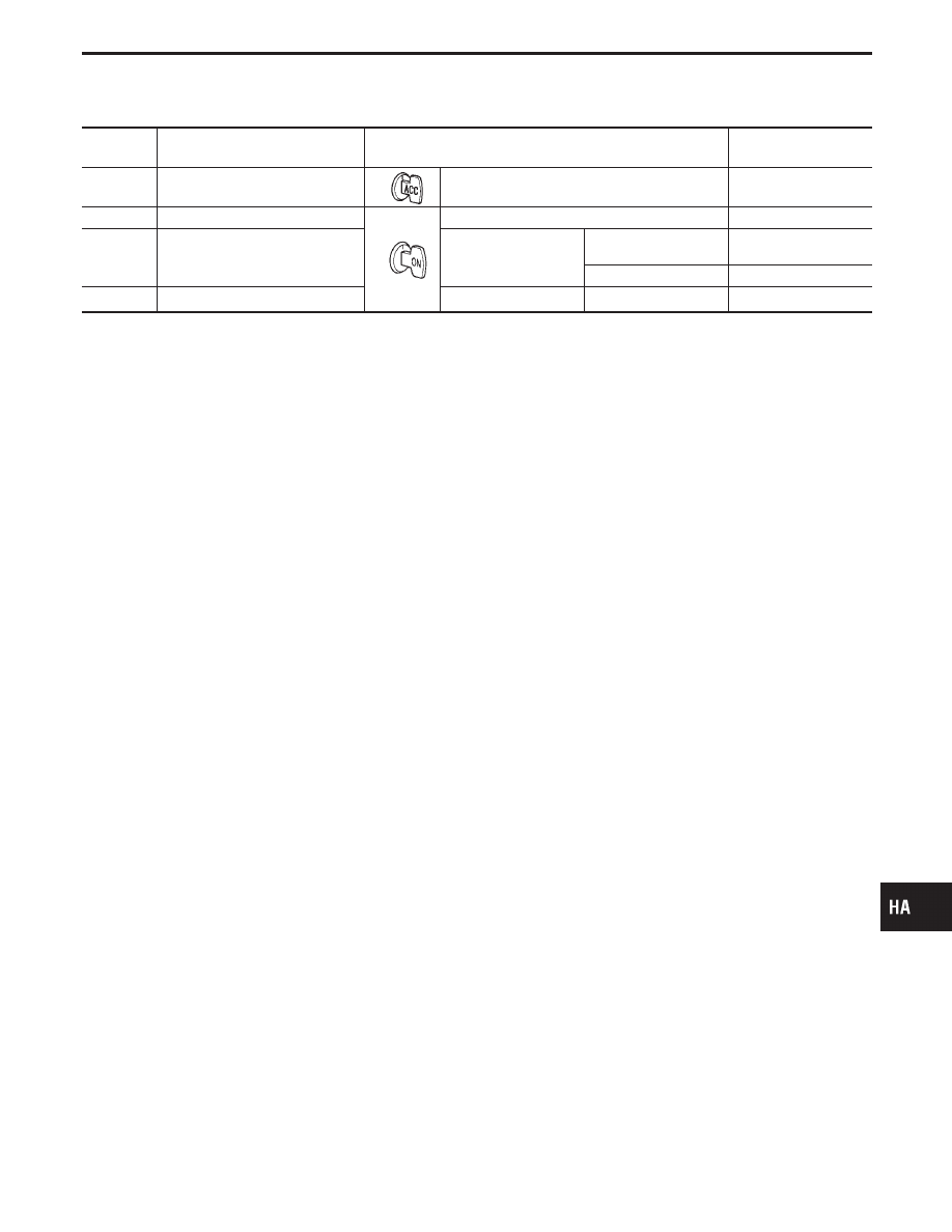
TERMINAL
NO.
ITEM
CONDITION
Voltage
V
33
Power source for ACC
—
Approximately 12
34
Blower motor feed back
Fan speed: Low
Approximately 7
35
Fan control AMP. control signal
Fan speed
Low, Middle low or
Middle high
Approximately 2.5 - 3.0
High
Approximately 9.0
36
Power supply for intake door motor
Recirculation switch
ON
,
OFF
*1
*1: When the motor is working, approx. 0V will be indicated. When the motor stops, approx. 12V will exist.
GI
MA
EM
LC
EC
FE
AT
PD
FA
RA
BR
ST
RS
BT
EL
IDX
TROUBLE DIAGNOSES
Auto Amp. Terminals and Reference Value
(Cont’d)
HA-85