Infiniti Q45 (FY33). Manual - part 468


  Index      Infiniti     Infiniti Q45 (FY33) - service repair manual 2001 year


Search            copyright infringement  


Content   ..  466  467  468  469   ..


Infiniti Q45 (FY33). Manual - part 468


Self-diagnosis

INTRODUCTION AND GENERAL DESCRIPTION

The self-diagnostic system diagnoses sensors, door motors,
blower motor and multiplex communication errors, etc. by system
line. Refer to applicable sections (items) for details. Shifting from
normal control to the self-diagnostic system is done as follows.
Start the engine (turn the ignition switch from “OFF” to “ON”). And
press

switch for at least 5 seconds. The

switch must be

pressed within 10 seconds after starting the engine (ignition switch
is turned “ON”). This system will be canceled by either pressing

switch or turning ignition switch “OFF”. Shifting from one step

to another is accomplished by means of rotating temperature con-
trol switch, as required.
Additionally shifting from STEP 5 to AUXILIARY MECHANISM is
accomplished by means of pushing

(Blower) switch.

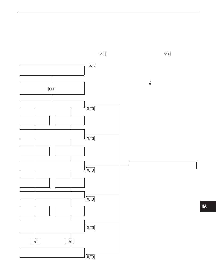
Without Navigation System

Note

Start engine.
(Ignition switch OFF

,

ON)

In 10 seconds after starting engine (ignition switch
is turned “ON”), press

switch for at least 5

seconds.

STEP 1 — LEDs and segments are checked.

G

Ignition switch: OFF

switch: ON

Turn temperature dial
clockwise.

Turn temperature dial
counterclockwise.

STEP 2 — Input signals from each sensor are
checked.

G

Ignition switch: OFF

switch: ON

Turn temperature dial
clockwise.

Turn temperature dial
counterclockwise.

STEP 3 — Mode door motor position switch is
checked.

G

Ignition switch: OFF

E

switch: ON

Self-diagnostic function is canceled.

Turn temperature dial
clockwise.

Turn temperature dial
counterclockwise.

STEP 4 — Actuators are checked.

G

Ignition switch: OFF

switch: ON

Turn temperature dial
clockwise.

Turn temperature dial
counterclockwise.

STEP 5 — Temperature detected by each sensor
is checked and multiplex communication errors are
detected.

G

Ignition switch: OFF

switch: ON

AUXILIARY MECHANISM — Temperature setting
trimmer

Ignition switch: OFF

switch: ON

Note:
Without engine running, STEP 4 and 5 are not useful
for some case because compressor does not oper-
ate.

GI

MA

EM

LC

EC

FE

AT

PD

FA

RA

BR

ST

RS

BT

EL

IDX

TROUBLE DIAGNOSES

H

H

H

H

H

H

H

HA-37

RHA157H

RHA179H

STEP-BY-STEP PROCEDURE

Turn ignition switch ON.

Set in self-diagnostic mode. Within 10 sec-
onds after starting engine (ignition switch is
turned “ON”.), press

switch for at

least 5 seconds.

STEP 1 - LEDs AND SEGMENT ARE
CHECKED.
Do all LEDs and segments illuminate?

Yes

E

No

Malfunctioning
switch, LED or fluorescent
display tube.
Replace front control unit.

Turn temperature dial clockwise.

Advance to self-diagnosis STEP 2?

Yes

E

No

Malfunctioning temperature
dial.
Replace front control unit.

Turn temperature dial counterclockwise.

G

Return to self-diagnosis STEP 1?

Yes

No

Turn temperature dial clockwise.

q

A

(Go to next page.)

TROUBLE DIAGNOSES

Self-diagnosis (Cont’d)

H

H

H

H

H

H

H

H

HA-38

RHA970D

RHA392G

RHA501A

q

A

STEP 2 - SENSOR CIRCUITS ARE
CHECKED FOR OPEN OR SHORT
CIRCUIT.
Does code No.

appear on the dis-

play?

Yes

No

H

Turn temperature
dial clockwise.

Refer to the following chart for malfunctioning code
No.
(If two or more sensors malfunction, corresponding
code Nos. blink respectively two times.)

*1: Conduct self-diagnosis STEP 2 under sunshine.

When conducting indoors, aim a light (more than
60W) at sunload sensor, otherwise Code No.

will indicate despite that sunload sensor is func-

tioning properly.

q

B

(Go to next page.)

Code No.

Malfunctioning sensor

(including circuits)

Reference

page

Ambient sensor

HA-90

In-vehicle sensor

HA-93

Intake sensor

HA-96

Sunload sensor*1

HA-97

Air mix door motor PBR

HA-102

Bi-level door motor PBR

HA-104

GI

MA

EM

LC

EC

FE

AT

PD

FA

RA

BR

ST

RS

BT

EL

IDX

TROUBLE DIAGNOSES

Self-diagnosis (Cont’d)

H

H

H

HA-39

RHA869D

RHA497A

RHA498A

q

B

STEP 3 - MODE DOOR AND INTAKE
DOOR POSITIONS ARE CHECKED.
Does code No.

appear on the dis-

play?

Yes

No

H

Turn temperature
dial clockwise.

Mode or (and) intake door motor position switch(es)
is (are) malfunctioning.
(If two or more mode or intake doors are out of
order, corresponding code numbers blink respec-
tively two times.)

*1: If mode door motor harness connector is

disconnected, the following display pattern will
appear.

,

,

,

,

,

,

*2: If intake door motor harness connector is

disconnected, the following display pattern will
appear.

,

,

,

q

C

(Go to next page.)

Code

No.*1 *2

Mode or intake door

position

Reference

page

VENT

HA-100

B/L

B/L 2

FOOT

FOOT/DEF

DEF

FRE

HA-109

20% FRE

REC

TROUBLE DIAGNOSES

Self-diagnosis (Cont’d)

H

H

H

HA-40


Content   ..  466  467  468  469   ..