Infiniti Q45 (FY33). Manual - part 460


  Index      Infiniti     Infiniti Q45 (FY33) - service repair manual 2001 year


Search            copyright infringement  


Content   ..  458  459  460  461   ..


Infiniti Q45 (FY33). Manual - part 460


SHA436FA

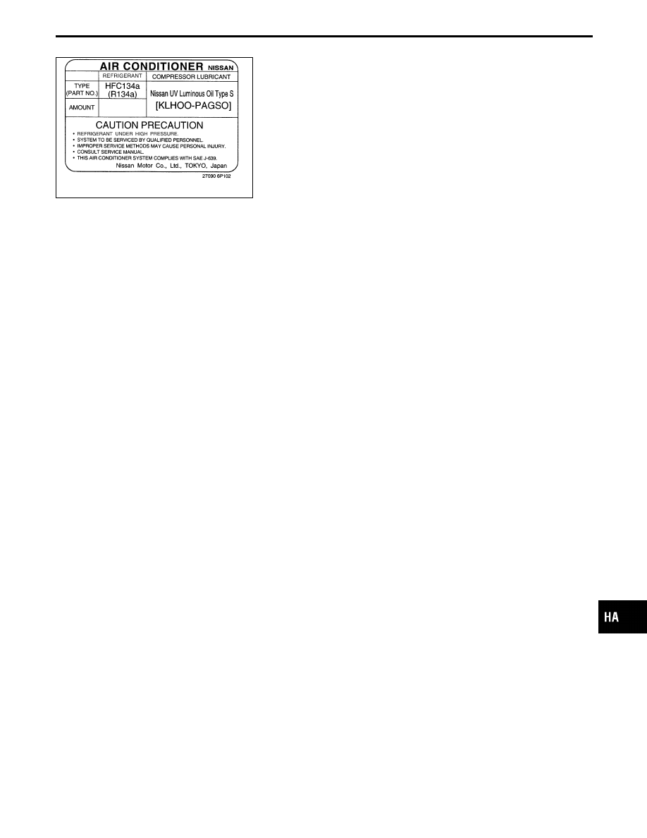
A/C Identification Label

Vehicles with factory installed fluorescent dye have this identifica-
tion label on the under side of hood.
NOTE:
Vehicles with factory installed fluorescent dye have a green label.
Vehicles without factory installed fluorescent dye have a blue label.

Precautions for Refrigerant Connection

A new type refrigerant connection has been introduced to all refrigerant lines except the following location.

I

Expansion valve to cooling unit

I

Condenser to liquid tank

FEATURES OF NEW TYPE REFRIGERANT CONNECTION

I

The O-ring is relocated in a groove for proper installation. This eliminates the chance of the O-ring being
caught in, or damaged by, the mating part. The sealing direction of the O-ring is now set vertically in rela-
tion to the contacting surface of the mating part to improve sealing characteristics.

I

The reaction force of the O-ring will not occur in the direction that causes the joint to pull out, thereby
facilitating piping connections.

GI

MA

EM

LC

EC

FE

AT

PD

FA

RA

BR

ST

RS

BT

EL

IDX

PRECAUTIONS AND PREPARATION

HA-5

SHA815E

O-RING AND REFRIGERANT CONNECTION

RHA895FB

CAUTION:

The new and former refrigerant connections use different O-ring configurations. Do not confuse
O-rings since they are not interchangeable. If a wrong O-ring is installed, refrigerant will leak at, or
around, the connection.

PRECAUTIONS AND PREPARATION

Precautions for Refrigerant Connection
(Cont’d)

HA-6

SHA814E

O-ring part numbers and specifications

Connection

type

O-ring

size

Part number

D

mm (in) W

mm (in)

New

8

92471 N8210

6.8 (0.268)

1.85 (0.0728)

Former

92470 N8200

6.07 (0.2390)

1.78 (0.0701)

New

12

92472 N8210

10.9 (0.429)

2.43 (0.0957)

Former

92475 71L00

11.0 (0.433)

2.4 (0.094)

New

16

92473 N8210

13.6 (0.535)

2.43 (0.0957)

Former

92475 72L00

14.3 (0.563)

2.3 (0.091)

New

19

92474 N8210

16.5 (0.650)

2.43 (0.0957)

WARNING:

Make sure all refrigerant is discharged into the recycling equipment and the pressure in the system
is less than atmospheric pressure. Then gradually loosen the discharge side hose fitting and remove
it.

CAUTION:

When replacing or cleaning refrigerant cycle components, observe the following.

I

When the compressor is removed, store it in the same position as it is when mounted on the car.
Failure to do so will cause lubricant to enter the low pressure chamber.

I

When connecting tubes, always use a torque wrench and a back-up wrench.

I

After disconnecting tubes, immediately plug all openings to prevent entry of dirt and moisture.

I

When installing an air conditioner in the vehicle, connect the pipes as the final stage of the opera-
tion. Do not remove the seal caps of pipes and other components until just before required for
connection.

I

Allow components stored in cool areas to warm to working area temperature before removing seal
caps. This prevents condensation from forming inside A/C components.

I

Thoroughly remove moisture from the refrigeration system before charging the refrigerant.

I

Always replace used O-rings.

I

When connecting tube, apply lubricant to circle of the O-rings shown in illustration. Be careful not
to apply lubricant to threaded portion.
Lubricant name: Nissan A/C System Oil Type S
Part number: KLH00-PAGS0

I

O-ring must be closely attached to dented portion of tube.

I

When replacing the O-ring, be careful not to damage O-ring and tube.

I

Connect tube until you hear it click, then tighten the nut or bolt by hand until snug.
Make sure that the O-ring is installed to tube correctly.

I

After connecting line, conduct leak test and make sure that there is no leakage from connections.
When the gas leaking point is found, disconnect that line and replace the O-ring. Then tighten
connections of seal seat to the specified torque.

GI

MA

EM

LC

EC

FE

AT

PD

FA

RA

BR

ST

RS

BT

EL

IDX

PRECAUTIONS AND PREPARATION

Precautions for Refrigerant Connection
(Cont’d)

HA-7

RHA861F

Precautions for Servicing Compressor

I

Plug all openings to prevent moisture and foreign matter from entering.

I

When the compressor is removed, store it in the same position as it is when mounted on the car.

I

When replacing or repairing compressor, follow “Maintenance of Lubricant Quantity in Compres-
sor” exactly. Refer to HA-128.

I

Keep friction surfaces between clutch and pulley clean. If the surface is contaminated, with
lubricant, wipe it off by using a clean waste cloth moistened with thinner.

I

After compressor service operation, turn the compressor shaft by hand more than five turns in
both directions. This will equally distribute lubricant inside the compressor. After the compressor
is installed, let the engine idle and operate the compressor for one hour.

I

After replacing the compressor magnet clutch, apply voltage to the new one and check for normal
operation.

PRECAUTIONS AND PREPARATION

Precautions for Refrigerant Connection
(Cont’d)

HA-8


Content   ..  458  459  460  461   ..