Infiniti Q45 (FY33). Manual - part 430
INSPECTION
Wash all parts, except for nonmetallic parts, clean with suitable
solvent and dry with compressed air.
Blow dirt and dust off of nonmetallic parts using compressed air.
Strut assembly
I
Oil oozing out around gland packing does not need strut
replacement.
If oil leakage is evident on spring seat, check piston rod gland
packing and O-ring.
If oil leakage occurs on welded portion of outer strut casing,
replace strut assembly.
I
If shock absorber itself is malfunctioning, replace as shock
absorber kit.
Gland packing
Check gland packing for oil leakage. Replace gland packing if
necessary.
Strut mounting insulator
Check cemented rubber-to-metal portion for melting or cracks.
Check rubber parts for deterioration. Replace if necessary.
Thrust seat
Check for cracks, deformation or other damage. Replace if neces-
sary.
Coil spring
Check for cracks, deformation or other damage. Replace if neces-
sary.
SFA141
ASSEMBLY
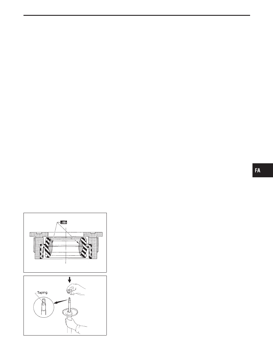
I
Lubricate sealing lip of gland packing.
SFA574
I
Install gland packing.
Cover piston rod with tape so as not to damage oil sealing lip.
GI
MA
EM
LC
EC
FE
AT
PD
RA
BR
ST
RS
BT
HA
EL
IDX
FRONT SUSPENSION
Coil Spring and Strut Assembly (Cont’d)
FA-19