Infiniti Q45 (FY33). Manual - part 425


  Index      Infiniti     Infiniti Q45 (FY33) - service repair manual 2001 year


Search            copyright infringement  


Content   ..  423  424  425  426   ..


Infiniti Q45 (FY33). Manual - part 425


CRANKSHAFT

Unit: mm (in)

Main journal dia. “Dm”

Grade No. 0

63.960 - 63.964 (2.5181 - 2.5183)

Grade No. 1

63.956 - 63.960 (2.5179 - 2.5181)

Grade No. 2

63.952 - 63.956 (2.5178 - 2.5179)

Grade No. 3

63.948 - 63.952 (2.5176 - 2.5178)

Grade No. 4

63.944 - 63.948 (2.5175 - 2.5176)

Grade No. 5

63.940 - 63.944 (2.5173 - 2.5175)

Pin journal dia. “Dp”

Grade No. 0

51.968 - 51.974 (2.0460 - 2.0462)

Grade No. 1

51.962 - 51.968 (2.0457 - 2.0460)

Grade No. 2

51.956 - 51.962 (2.0455 - 2.0457)

Center distance “r”

37.996 - 38.004 (1.4959 - 1.4962)

Out-of-round (X − Y)

Standard

Less than 0.005 (0.0002)

Taper (A − B)

Standard

Less than 0.005 (0.0002)

Runout [TIR]

Standard

Less than 0.05 (0.0020)

Limit

0.1 (0.004)

Free end play

Standard

0.10 - 0.26 (0.0039 - 0.0102)

Limit

0.30 (0.0118)

SEM954C

EM715

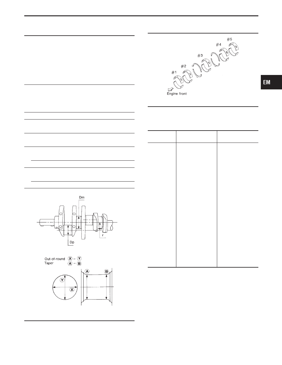
AVAILABLE MAIN BEARING

SEM753C

Standard size

Unit: mm (in)

Grade

number

Thickness “T”

Identification

color (mark)

0

2.484 - 2.487

(0.0978 - 0.0979)

Black (A)

1

2.486 - 2.489

(0.0979 - 0.0980)

Brown (B)

2

2.488 - 2.491

(0.0980 - 0.0981)

Green (C)

3

2.490 - 2.493

(0.0980 - 0.0981)

Yellow (D)

4

2.492 - 2.495

(0.0981 - 0.0982)

Blue (E)

5

2.494 - 2.497

(0.0982 - 0.0983)

Pink (F)

6

2.496 - 2.499

(0.0983 - 0.0984)

No color (G)

7

2.498 - 2.501

(0.0983 - 0.0985)

White (H)

8

2.500 - 2.503

(0.0984 - 0.0985)

Red (I)

9

2.502 - 2.505

(0.0985 - 0.0986)

Black/Black (J)

10

2.504 - 2.507

(0.0986 - 0.987)

Yellow/Yellow (K)

GI

MA

LC

EC

FE

AT

PD

FA

RA

BR

ST

RS

BT

HA

EL

IDX

SERVICE DATA AND SPECIFICATIONS (SDS)

Inspection and Adjustment (Cont’d)

EM-61

Undersize

Unit: mm (in)

Thickness

Main journal

diameter “Dm”

0.25

(0.0098)

2.617 - 2.625

(0.1030 - 0.1033)

Grind so that bearing

clearance is the speci-

fied value.

AVAILABLE CONNECTING ROD BEARING

Connecting rod bearing

Standard size

Unit: mm (in)

Grade

number

Thickness “T”

Identification

color (mark)

0

1.500 - 1.503

(0.0591 - 0.0592)

No color (A)

1

1.503 - 1.506

(0.0592 - 0.0593)

Brown (B)

2

1.506 - 1.509

(0.0593 - 0.0594)

Green (C)

Undersize

Unit: mm (in)

Thickness

Crank pin journal

diameter “Dp”

0.08 (0.0031)

1.541 - 1.549

(0.0607 - 0.0610)

Grind so that bearing

clearance is the

specified value.

0.12 (0.0047)

1.561 - 1.569

(0.0615 - 0.0618)

0.25 (0.0098)

1.626 - 1.634

(0.0640 - 0.0643)

Bearing clearance

Unit: mm (in)

Main bearing clearance

Standard

0.006 - 0.020 (0.0002 - 0.0008)

Limit

0.030 (0.0012)

Connecting rod bearing clearance

Standard

0.020 - 0.045 (0.0008 - 0.0018)

Limit

0.055 (0.0022)

MISCELLANEOUS COMPONENTS

Unit: mm (in)

Drive plate

Runout [TIR]*

Less than 0.20 (0.0079)

*Total indicator reading

SERVICE DATA AND SPECIFICATIONS (SDS)

Inspection and Adjustment (Cont’d)

EM-62

FRONT AXLE &

FRONT SUSPENSION

SECTION

FA

CONTENTS

PRECAUTIONS AND PREPARATION............................2

Supplemental Restraint System (SRS)

AIR

BAG

and

SEAT BELT PRE-TENSIONER

...............2

Precautions for Brake System.....................................2
Special Service Tools ..................................................3
Commercial Service Tools ...........................................4

NOISE, VIBRATION AND HARSHNESS (NVH)
TROUBLESHOOTING 
.....................................................5

NVH Troubleshooting Chart.........................................5

FRONT SUSPENSION SYSTEM ....................................6
ON-VEHICLE SERVICE ..................................................7

Front Axle and Front Suspension Parts ......................7
Front Wheel Bearing....................................................8
Front Wheel Alignment ................................................9

FRONT AXLE ................................................................12

Wheel Hub and Knuckle............................................12
ABS Sensor Rotor .....................................................15

FRONT SUSPENSION ..................................................16

Coil Spring and Strut Assembly.................................17
Tension Rod and Stabilizer Bar.................................21
Transverse Link Assembly.........................................22

ACTIVE DAMPER SUSPENSION.................................23

System Components .................................................23
Component Description .............................................23
Active Damper Suspension Configuration.................25
Active Damper ...........................................................26
Removal and Installation ...........................................27

TROUBLE DIAGNOSES ...............................................28

How to Perform Trouble Diagnoses for Quick
and Accurate Repair 
..................................................28

Symptom Chart..........................................................29
Fail-safe Remarks......................................................30
Preliminary Check......................................................31
Component Parts and Harness Connector
Locations
....................................................................32
Schematic ..................................................................33
Wiring Diagram ..........................................................34
Self-diagnoses ...........................................................39
CONSULT-II Inspection Procedure............................41

TROUBLE DIAGNOSES FOR SELF-DIAGNOSTIC
ITEMS
.............................................................................
47

Diagnostic Procedure 1 (Vehicle speed sensor) .......47
Diagnostic Procedure 2 (Steering angle sensor) ......48
Diagnostic Procedure 3 (Stop lamp switch) ..............49
Diagnostic Procedure 4 (Vertical G sensor)..............50

TROUBLE DIAGNOSES FOR SYMPTOMS.................51

Diagnostic Procedure 5 (SPORT indicator does
not come on when ignition switch is turned on.).......
51
Diagnostic procedure 6 (Hard or soft feel)................53
Diagnostic Procedure 7 (Heavy steering
operation during stationary turns)..............................
56
Diagnostic Procedure 8 (Light steering during
high-speed operation)................................................
57

TROUBLE DIAGNOSES FOR ACTIVE DAMPER
SUSPENSION 
................................................................58

Electrical Component Inspection ...............................58

SERVICE DATA AND SPECIFICATIONS (SDS) ..........60

General Specifications...............................................60
Inspection and Adjustment ........................................60

GI

MA

EM

LC

EC

FE

AT

PD

RA

BR

ST

RS

BT

HA

EL

IDX

Supplemental Restraint System (SRS) “AIR
BAG” and “SEAT BELT PRE-TENSIONER”

The Supplemental Restraint System such as “AIR BAG” and “SEAT BELT PRE-TENSIONER” used along with
a seat belt, helps to reduce the risk or severity of injury to the driver and front passenger for certain types of
collision. The SRS system composition which is available to INFINITI Q45 is as follows:

I

For a frontal collision
The Supplemental Restraint System consists of driver air bag module (located in the center of the steer-
ing wheel), front passenger air bag module (located on the instrument panel on passenger side), seat belt
pre-tensioners, a diagnosis sensor unit, warning lamp, wiring harness and spiral cable.

I

For a side collision
The Supplemental Restraint System consists of front side air bag module (located in the outer side of front
seat), satellite sensor, diagnosis sensor unit (one of components of air bags for a frontal collision), wiring
harness, warning lamp (one of components of air bags for a frontal collision).

Information necessary to service the system safely is included in the RS section of this Service Manual.

WARNING:

I

To avoid rendering the SRS inoperative, which could increase the risk of personal injury or death
in the event of a collision which would result in air bag inflation, all maintenance should be per-
formed by an authorized INFINITI dealer.

I

Improper maintenance, including incorrect removal and installation of the SRS, can lead to per-
sonal injury caused by unintentional activation of the system. For removal of Spiral Cable and Air
Bag Module, see the RS section.

I

Do not use electrical test equipment on any circuit related to the SRS unless instructed to in this
Service Manual. Spiral cable and wiring harnesses covered with yellow insulation tape (except
satellite sensor and side air bag module) either just before the harness connectors or for the com-
plete harness are related to the SRS.

SBR686C

Precautions for Brake System

I

When installing rubber parts, final tightening must be car-
ried out under unladen condition* with tires on ground.
*: Fuel, radiator coolant and engine oil full. Spare tire,

jack, hand tools and mats in designated positions.

I

After installing removed suspension parts, check wheel
alignment and adjust if necessary.

I

Use flare nut wrench when removing or installing brake
tubes.

I

Always torque brake lines when installing.

PRECAUTIONS AND PREPARATION

FA-2


Content   ..  423  424  425  426   ..