Infiniti Q45 (FY33). Manual - part 419


  Index      Infiniti     Infiniti Q45 (FY33) - service repair manual 2001 year


Search            copyright infringement  


Content   ..  417  418  419  420   ..


Infiniti Q45 (FY33). Manual - part 419


SEM938C

SEM008A

2.

If it exceeds the limit, check valve to valve guide clearance.

a.

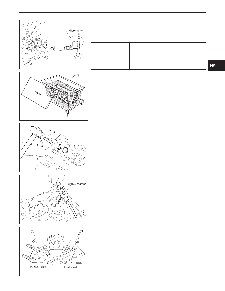
Measure valve stem diameter and valve guide inner diameter.

b.

Check that clearance is within specification.

Valve to valve guide clearance:

Unit: mm (in)

Standard

Limit

Intake

0.029 - 0.052

(0.0011 - 0.0020)

0.086 (0.0034)

Exhaust

0.035 - 0.051

(0.0014 - 0.0020)

0.092 (0.0036)

c.

If it exceeds the limit, replace valve or valve guide.

VALVE GUIDE REPLACEMENT

1.

To remove valve guide, heat cylinder head to 110 to 130°C
(230 to 266°F).

SEM931C

2.

Drive out valve guide with a press [under a 20 kN (2 ton, 2.2
US ton, 2.0 Imp ton) pressure] or hammer and suitable tool.

SEM932C

3.

Ream cylinder head valve guide hole.

Valve guide hole diameter
(for service parts):

Intake

11.175 - 11.196 mm (0.4400 - 0.4408 in)

Exhaust

12.175 - 12.196 mm (0.4793 - 0.4802 in)

SEM933C

4.

Heat cylinder head to 110 to 130°C (230 to 266°F) and press
service valve guide onto cylinder head.

Projection “L”:

17.15 - 17.35 mm (0.6725 - 0.6831 in)

GI

MA

LC

EC

FE

AT

PD

FA

RA

BR

ST

RS

BT

HA

EL

IDX

CYLINDER HEAD

Inspection (Cont’d)

EM-37

SEM932C

5.

Ream valve guide.

Finished size:

Intake

7.000 - 7.018 mm (0.2756 - 0.2763 in)

Exhaust

8.000 - 8.011 mm (0.3150 - 0.3154 in)

SEM934C

VALVE SEATS

Check valve seats for pitting at contact surface. Resurface or
replace if excessively worn.

I

Before repairing valve seats, check valve and valve guide
for wear. If they have worn, replace them. Then correct
valve seat.

I

Use both hands to cut valve seat uniformly.

SEM795A

REPLACING VALVE SEAT FOR SERVICE PARTS

1.

Bore out old seat until it collapses. Set machine depth stop so
that boring cannot contact bottom face of seat recess in cylin-
der head.

2.

Ream cylinder head recess.

Reaming bore for service valve seat
Oversize [0.5 mm (0.020 in)]:

Intake 39.500 - 39.516 mm (1.5551 - 1.5557 in)
Exhaust 34.500 - 34.516 mm (1.3583 - 1.3589 in)

Use the valve guide center for reaming to ensure valve seat
will have the correct fit.

SEM892B

3.

Heat cylinder head to 110 to 130°C (230 to 266°F).

4.

Press fit valve seat until it seats on the bottom.

5.

Cut or grind valve seat using suitable tool at the specified
dimensions as shown in SDS (EM-58).

6.

After cutting, lap valve seat with abrasive compound.

7.

Check valve seating condition.

Seat face angle “

α

”: 44°53

- 45°07

deg.

Contacting width “W”:

Intake

1.05 - 1.35 mm (0.0413 - 0.0531 in)

Exhaust

1.25 - 1.55 mm (0.0492 - 0.0610 in)

SEM621F

8.

Use a depth gauge to measure the distance between the
mounting surface of the cylinder head spring seat and the
valve stem end. If the distance is shorter than specified, repeat
step 5 above to adjust it. If it is longer, replace the valve seat
with a new one.

Valve seat resurface limit “L”:

Intake

46.25 - 46.95 mm (1.8209 - 1.8484 in)

Exhaust

46.21 - 46.91 mm (1.8193 - 1.8468 in)

CYLINDER HEAD

Inspection (Cont’d)

EM-38

SEM188A

VALVE DIMENSIONS

Check dimensions in each valve. For dimensions, refer to SDS
(EM-57).
When valve head has been worn down to 0.5 mm (0.020 in) in
margin thickness, replace valve.
Grinding allowance for valve stem tip is 0.2 mm (0.008 in) or
less.

SEM288A

VALVE SPRING

Squareness

1.

Measure dimension “S”.

Out-of-square “S”:

Less than 2.0 mm (0.079 in)

2.

If it exceeds the limit, replace spring.

EM113

Pressure

Check valve spring pressure at specified spring height.

Pressure:

Standard

535.5 N (54.6 kg, 120.4 lb)
at height 26.8 mm (1.055 in)

Limit

More than 477.6 N (48.7 kg, 107.4 lb)
at height 26.8 mm (1.055 in)

If it exceeds the limit, replace spring.

SEM936C

HYDRAULIC LASH ADJUSTER

1.

Check contact and sliding surfaces for wear or scratches.

2.

Check diameter of lash adjuster.

Outer diameter:

16.980 - 16.993 mm (0.6685 - 0.6690 in)

SEM937C

3.

Check lash adjuster guide inner diameter.

Inner diameter:

17.000 - 17.020 mm (0.6693 - 0.6701 in)

Standard clearance between lash adjuster and
adjuster guide:

0.007 - 0.040 mm (0.0003 - 0.0016 in)

GI

MA

LC

EC

FE

AT

PD

FA

RA

BR

ST

RS

BT

HA

EL

IDX

CYLINDER HEAD

Inspection (Cont’d)

EM-39

SEM486F

Inspection of air entering

I

Check if air has entered inside of hydraulic lash adjuster when
it is installed or if abnormal sound occurs when engine is run-
ning.

I

Press rocker arm pivot firmly around the cam base circle as
shown in figure.

Depression limit: 1.0 mm (0.039 in)

I

If depression dimension is greater than 1.0 mm (0.039 in), air
may have entered the high-pressure chamber of hydraulic lash
adjuster. Perform the following procedures to bleed air from the
adjuster.

SEM487F

Air bleeding

I

Remove hydraulic lash adjuster. Place adjuster in container of
engine oil. While pressing plunger down as shown in the figure,
lightly press check ball with a narrow rod.

I

Air bleeding is accomplished when the plunger is pressed and
does not spring back.

CAUTION:

I

Be especially careful not to damage the check ball.

I

If air bleeding does not remove air, replace the hydraulic
lash adjuster assembly.

I

Do not disassemble hydraulic lash adjuster.

SEM085D

Assembly

1.

Install valve component parts.

I

Always use new valve oil seal. Refer to OIL SEAL
REPLACEMENT (EM-27).

I

Before installing valve oil seal, install valve spring seat.

I

Install valve spring (uneven pitch type) with its narrow
pitch side toward cylinder head side (Paint mark).

I

After installing valve components, tap valve stem tip with
a plastic hammer to assure a proper fit.

SEM482F

Installation

1.

Install cylinder head gaskets.
Remove all oil and debris from the cylinder head and block
mating surfaces.
Always use new gaskets.
Refer to the figure to determine the difference between left and
right gaskets.

SEM473F

2.

Install cylinder heads.
Check that camshaft key and camshaft knock pins are located
in positions shown in the figure. Install cylinder heads on block.
Be careful not to damage or scratch cylinder head gaskets
during installation.

CYLINDER HEAD

Inspection (Cont’d)

EM-40


Content   ..  417  418  419  420   ..