Infiniti Q45 (FY33). Manual - part 414


  Index      Infiniti     Infiniti Q45 (FY33) - service repair manual 2001 year


Search            copyright infringement  


Content   ..  412  413  414  415   ..


Infiniti Q45 (FY33). Manual - part 414


SEM422F

SEM423F

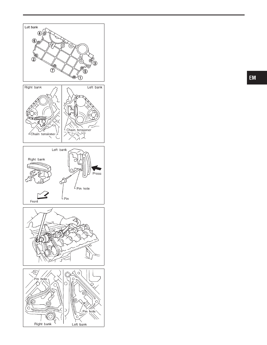
12. Remove upper chain tensioner.

SEM424F

I

Press tensioner in and insert 1 mm (0.04 in) diameter pin in pin
hole. After securing tensioner, remove bolts.

SEM470F

13. Remove camshaft sprocket bolt while holding the hexagonal

part of camshaft with wrench.
Remove camshaft sprockets.

I

Apply paint to upper timing chain and camshaft sprockets
for alignment during installation.

SEM425F

14. Remove right and left tensioner covers from front covers.

I

Press tensioner in and insert 1 mm (0.04 in) diameter pin in pin
hole.

15. Remove idler sprocket bolts.

GI

MA

LC

EC

FE

AT

PD

FA

RA

BR

ST

RS

BT

HA

EL

IDX

TIMING CHAIN

Removal (Cont’d)

EM-17

16. Remove chain guide between No. 1 camshaft bracket.
17. Remove cylinder head assembly. Refer to “CYLINDER HEAD”

(EM-32).

18. Remove upper timing chain.
19. Remove idler sprocket.

I

Apply paint to lower timing chain and idler sprocket for
alignment during installation.

20. Remove oil pan. Refer to “OIL PAN” (EM-11).

SEM471F

21. Remove front cover.

Loosen bolts in the numerical order shown in the figure and
then remove them.

22. Remove lower chain tensioner.
23. Remove oil pump drive chain.
24. Remove slack guide and chain guide.
25. Remove lower timing chain together with crankshaft sprocket.

SEM472F

Inspection

TIMING CHAIN

Check for cracks and excessive wear at roller links. Replace
if necessary.

TIMING CHAIN

Removal (Cont’d)

EM-18

Installation

SEM426F

I

Refer to the figure and align the mating marks on each
sprocket and timing chain.

SEM473F

1.

Check that crankshaft key faces upward at 45° angle in direc-
tion of left bank axis when viewed from the front.

GI

MA

LC

EC

FE

AT

PD

FA

RA

BR

ST

RS

BT

HA

EL

IDX

TIMING CHAIN

EM-19

SEM427F

2.

Install lower timing chain on right bank.
Align the mating marks on timing chain and crankshaft
sprocket and install on crankshaft.

SEM474F

3.

Install crankshaft sprocket so thick boss faces cylinder block.

SEM428F

4.

Install slack guide and chain guide.
Refer to figure and check that bolt assembly is correctly posi-
tioned.

Position

Item

q

1

q

2

q

3

q

4

,

q

5

,

q

6

Flange thickness

mm (in)

2.5

(0.098)

2.5

(0.098)

Sleeve length

mm (in)

23.5

(0.925)

23.5

(0.925)

Hexagonal hole screw hole
presence

No

Yes

: 13 - 19 N

m (1.3 - 1.9 kg-m, 9 - 14 ft-lb)

SEM429F

5.

Install lower timing chain on left bank.
Align the mating marks on timing chain and crankshaft
sprocket and install on crankshaft.
Install crankshaft with boss side facing engine.
(Install in same manner as right bank.)

6.

Install left bank slack guide and chain guide.
Refer to figure and make sure bolts are installed correctly.

TIMING CHAIN

Installation (Cont’d)

EM-20


Content   ..  412  413  414  415   ..