Infiniti Q45 (FY33). Manual - part 412
SEM623FA
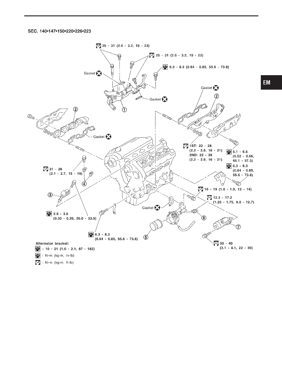
q
1
Water inlet and outlet
q
2
Exhaust manifold
q
3
Ignition coil with power transistor
q
4
Knock sensor
q
5
Oil filter
q
6
Oil pressure switch
q
7
Starter motor
GI
MA
LC
EC
FE
AT
PD
FA
RA
BR
ST
RS
BT
HA
EL
IDX
OUTER COMPONENT PARTS
EM-9