Infiniti Q45 (FY33). Manual - part 373
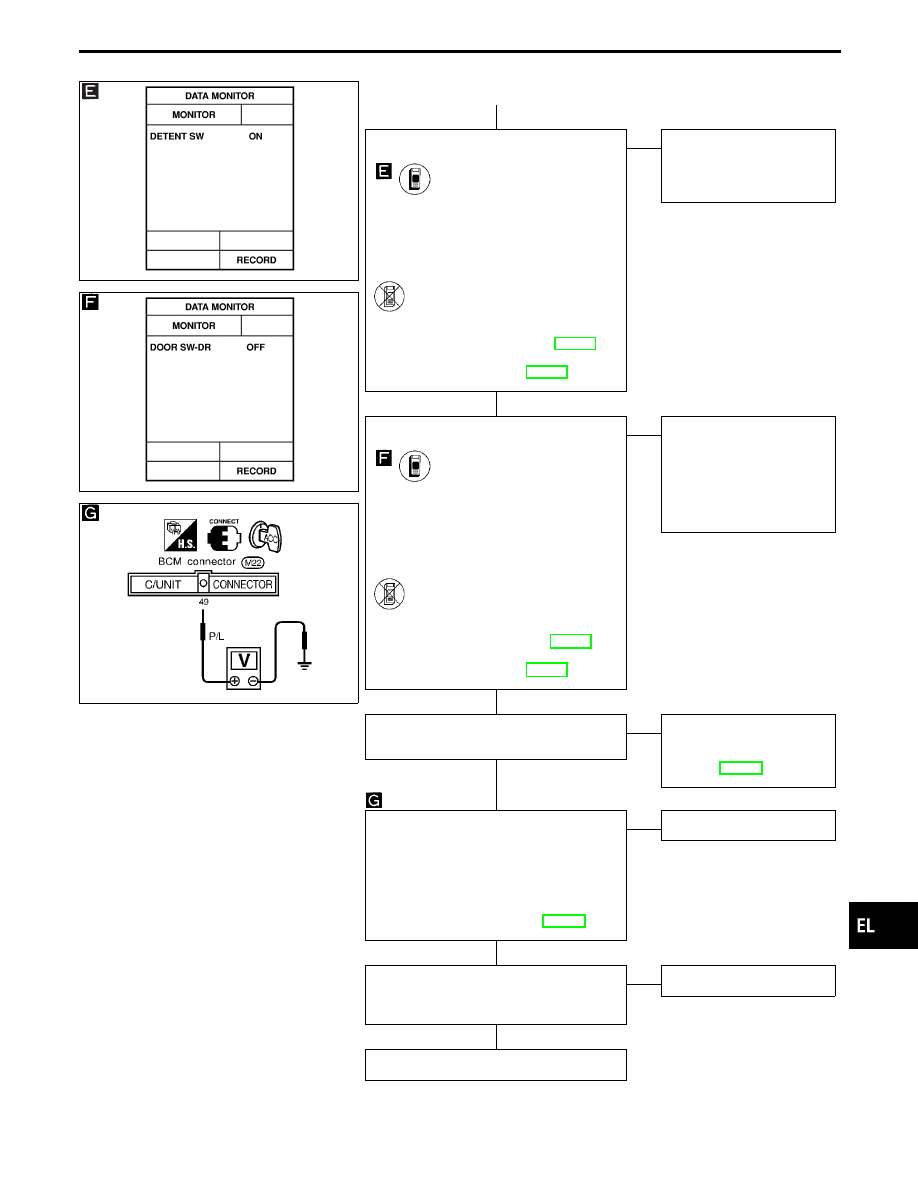
SEL554W
SEL556W
SEL681UA
q
A
CHECK DETENTION SWITCH INPUT
SIGNAL.
CONSULT-II
See “DETENT SW” in DATA MONITOR
mode.
“DETENT SW” should be “ON” when
setting A/T selector lever in “P” posi-
tion.
-------------------------------------------------------------------------------------------------------------------------------------- OR --------------------------------------------------------------------------------------------------------------------------------------
ON BOARD
Check detention switch operation in switch
monitor (Mode II) mode.
(Refer to On board Diagnoses, EL-299.)
Refer to wiring diagram in EL-448.
OK
E
NG
Check the following.
I
Detention switch
I
Harness for open or
short
CHECK DRIVER DOOR SWITCH INPUT
SIGNAL.
CONSULT-II
See “DOOR SW DR” in DATA MONITOR
mode.
When driver’s door is open:
DOOR SW-DR
ON
When driver’s door is closed:
DOOR SW-DR
OFF
-------------------------------------------------------------------------------------------------------------------------------------- OR --------------------------------------------------------------------------------------------------------------------------------------
ON BOARD
Check driver’s door switch operation in
Switch monitor (Mode II) mode.
(Refer to On board Diagnoses EL-299.)
Refer to wiring diagram in EL-448.
OK
E
NG
Check the following.
I
Driver door switch
I
Driver door switch
ground condition
I
Harness for open or
short between driver
door switch and BCM
CHECK VEHICLE SPEED SENSOR.
Does speedometer operate normally?
Yes
E
No
Check speedometer and
vehicle speed sensor cir-
cuit.
Refer to EL-149.
CHECK VEHICLE SPEED SENSOR
PULL UP VOLTAGE.
1. Turn ignition switch to ACC.
2. Check voltage between BCM terminal
q
49
and ground.
Approx. 5V should exist.
Refer to wiring diagram in EL-448.
OK
E
NG
Replace BCM.
Check harness for open or short between
BCM terminal
q
49
and combination meter
terminal
q
16
.
OK
E
NG
Repair harness.
INSPECTION END
GI
MA
EM
LC
EC
FE
AT
PD
FA
RA
BR
ST
RS
BT
HA
IDX
AUTOMATIC DRIVE POSITIONER — IVMS
Trouble Diagnoses (Cont’d)
H
H
H
H
H
H
EL-483