Infiniti Q45 (FY33). Manual - part 369
SEL544W
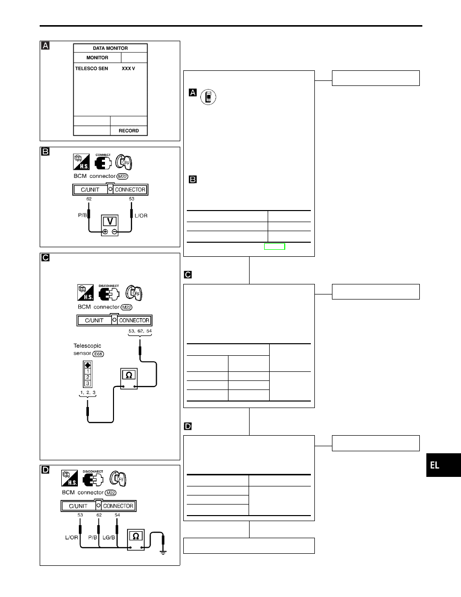
DIAGNOSTIC PROCEDURE 4
(Telescopic sensor check)
SEL990U
SEL991U
SEL992U
CHECK TELESCOPIC SENSOR INPUT
SIGNAL.
CONSULT-II
See “TELESCO SEN” in DATA MONITOR
mode.
Steering column in the extreme front end
position:
Approx. 4.5V
Steering column in the extreme rear end
position:
Approx. 0.5V
-------------------------------------------------------------------------------------------------------------------------------------- OR --------------------------------------------------------------------------------------------------------------------------------------
TESTER
Check voltage between BCM terminals
q
53
and
q
62
.
Refer to wiring diagram in EL-450.
NG
E
OK
Telescopic sensor is OK.
CHECK TELESCOPIC SENSOR OPEN
CIRCUIT.
1. Disconnect BCM connector and tele-
scopic sensor connector.
2. Check harness continuity between BCM
connector and telescopic sensor con-
nector.
OK
E
NG
Repair harness.
CHECK TELESCOPIC SENSOR SHORT
CIRCUIT.
Check harness continuity between BCM
connector terminals and ground.
OK
E
NG
Repair harness.
Replace telescopic sensor.
Steering column position
Voltage
Extreme front end
Approx. 4.5V
Extreme rear end
Approx. 0.5V
Terminals
Continuity
BCM
Telescopic
sensor
q
53
q
1
Yes
q
62
q
2
q
54
q
3
Terminals
Continuity
q
53
- ground
No
q
62
- ground
q
54
- ground
GI
MA
EM
LC
EC
FE
AT
PD
FA
RA
BR
ST
RS
BT
HA
IDX
AUTOMATIC DRIVE POSITIONER — IVMS
Trouble Diagnoses (Cont’d)
H
H
H
EL-467