Infiniti Q45 (FY33). Manual - part 339


  Index      Infiniti     Infiniti Q45 (FY33) - service repair manual 2001 year


Search            copyright infringement  


Content   ..  337  338  339  340   ..


Infiniti Q45 (FY33). Manual - part 339


SEL532W

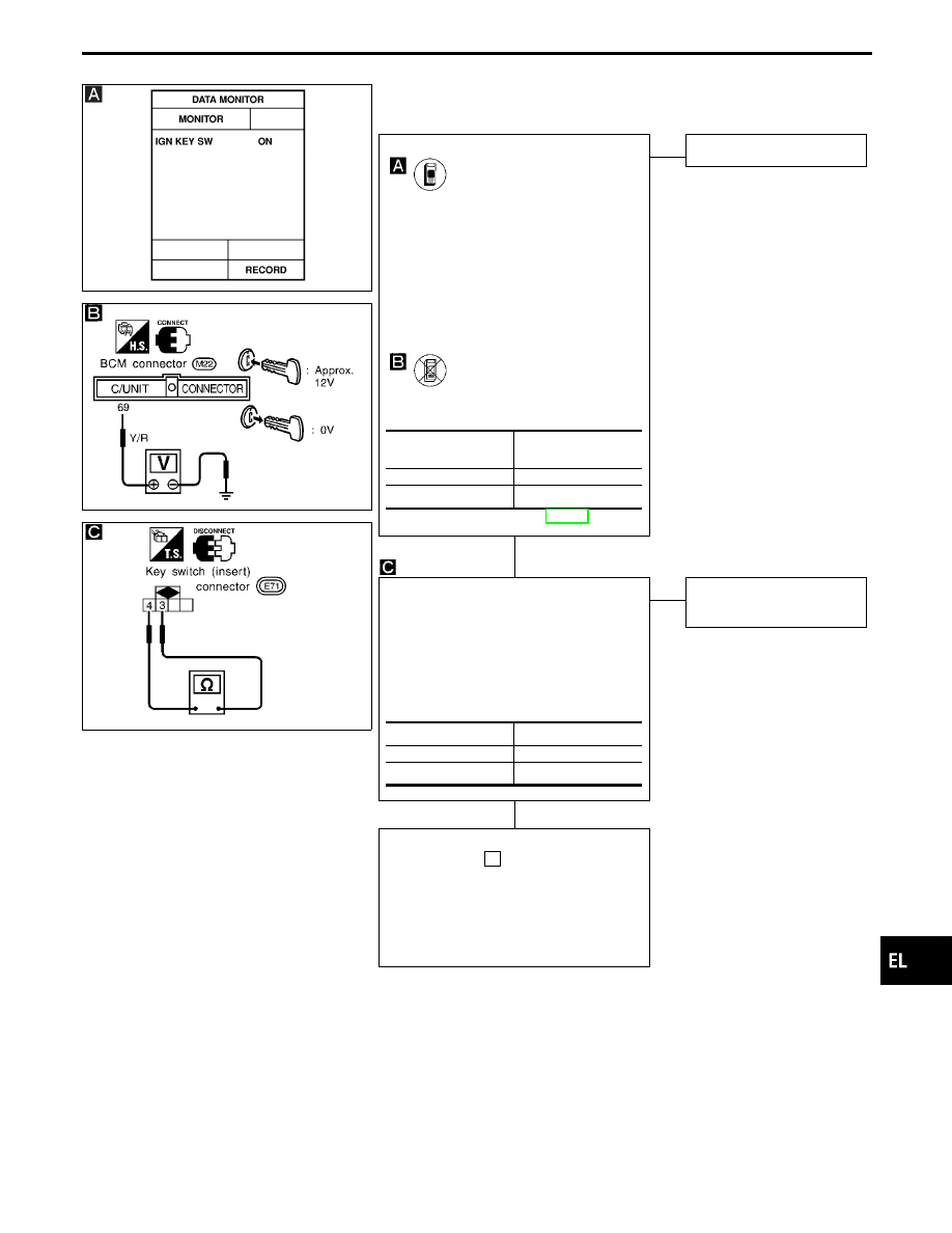
DIAGNOSTIC PROCEDURE 2

[Key switch (Insert) check]

SEL916V

SEL907U

CHECK KEY SWITCH INPUT SIGNAL.

CONSULT-II

See “IGN KEY SW” in DATA MONITOR
mode.
When key is inserted in ignition key cylin-
der:

IGN KEY SW

ON

When key is removed from ignition key
cylinder:

IGN KEY SW

OFF

-------------------------------------------------------------------------------------------------------------------------------------- OR --------------------------------------------------------------------------------------------------------------------------------------

TESTER

Check voltage between BCM terminal

q

69

and ground.

Refer to wiring diagram in EL-335.

NG

E

OK

Ignition key switch is OK.

CHECK KEY SWITCH.
1. Disconnect key switch connector.
2. Check continuity between key switch

(insert) terminals

q

3

and

q

4

when key

is inserted in ignition key cylinder and
key is removed from ignition key cylin-
der.

OK

E

NG

Replace key switch
(insert).

Check the following.

I

10A fuse [No.

28

, located in fuse block

(J/B)]

I

Harness for open or short between key
switch and fuse

I

Harness for open or short between BCM
and key switch

Condition of key

switch

Voltage V

Key is inserted.

Approx. 12

Key is removed.

0

Condition

Continuity

Key is inserted.

Yes

Key is removed.

No

GI

MA

EM

LC

EC

FE

AT

PD

FA

RA

BR

ST

RS

BT

HA

IDX

POWER DOOR LOCK — IVMS

Trouble Diagnoses (Cont’d)

H

H

EL-347

SEL561W

DIAGNOSTIC PROCEDURE 3

(Lock & unlock switch check)

CHECK DOOR LOCK & UNLOCK
SWITCH INPUT SIGNAL.

CONSULT-II

See “DOOR LK SW-LK or UN” in DATA
MONITOR mode.
When lock & unlock switch is turned to
lock:

DOOR LK SW-LK

ON

When lock & unlock switch is turned to
unlock:

DOOR LK SW-UN

ON

-------------------------------------------------------------------------------------------------------------------------------------- OR --------------------------------------------------------------------------------------------------------------------------------------

ON BOARD

Check door lock & unlock switch operation
in Switch monitor (Mode II) mode. (Refer
to On board Diagnosis, EL-299.)

NG

E

OK

Lock & unlock switch is
OK.

Replace driver door control unit (LCU01).

POWER DOOR LOCK — IVMS

Trouble Diagnoses (Cont’d)

H

EL-348

SEL537W

DIAGNOSTIC PROCEDURE 4-(1)
(Door key cylinder lock switch check)

SEL871W

SEL909U

CHECK DOOR KEY CYLINDER SWITCH
INPUT SIGNAL (LOCK SIGNAL).

CONSULT-II

See “KEY CYL LK” in DATA MONITOR
mode.
“KEY CYL LK” should be “ON” when
key inserted in door key cylinder was
turned to lock.

-------------------------------------------------------------------------------------------------------------------------------------- OR --------------------------------------------------------------------------------------------------------------------------------------

TESTER

Check voltage between LCU01/02 termi-
nal

q

1

and ground.

Refer to wiring diagram in EL-336 or 337.

NG

E

OK

Door key cylinder switch
(lock) is OK.

CHECK DOOR KEY CYLINDER
SWITCH.
1. Disconnect door key cylinder switch

connector.

2. Check continuity between door key cyl-

inder switch terminals.

OK

E

NG

Replace door key cylinder
switch.

Check the following.

I

Door key cylinder switch ground circuit

I

Harness for open or short between LCU
and door key cylinder switch

Key position

Voltage V

Neutral/Unlock

Approx. 5

Lock

0

Terminals

Key position

Continuity

LH:

q

3

-

q

2

RH:

q

1

-

q

2

Neutral/

Unlock

No

Lock

Yes

GI

MA

EM

LC

EC

FE

AT

PD

FA

RA

BR

ST

RS

BT

HA

IDX

POWER DOOR LOCK — IVMS

Trouble Diagnoses (Cont’d)

H

H

EL-349

SEL538W

DIAGNOSTIC PROCEDURE 4-(2)
(Door key cylinder unlock switch check)

SEL952V

SEL913U

CHECK DOOR KEY CYLINDER SWITCH
INPUT SIGNAL (UNLOCK SIGNAL).

CONSULT-II

See “KEY CYL UN” in DATA MONITOR
mode.
“KEY CYL UN” should be “ON” when
key inserted in door key cylinder was
turned to unlock.

-------------------------------------------------------------------------------------------------------------------------------------- OR --------------------------------------------------------------------------------------------------------------------------------------

TESTER

Check voltage between BCM terminals

q

27

or

q

31

and ground.

Refer to wiring diagram in EL-335.

NG

E

OK

Door key cylinder switch
(unlock) is OK.

CHECK DOOR KEY CYLINDER
SWITCH.
1. Disconnect door key cylinder switch

connector.

2. Check continuity between door key cyl-

inder switch terminals.

OK

E

NG

Replace door key cylinder
switch.

Check the following.

I

Door key cylinder switch ground circuit

I

Harness for open or short between BCM
and door key cylinder switch

Terminals

Key

position

Voltage

V

!

@

LH

q

31

Ground

Neutral/

Lock

Approx.

12

Unlock

0

RH

q

27

Ground

Neutral/

Lock

Approx.

12

Unlock

0

Terminals

Key position

Continuity

LH:

q

1

-

q

2

RH:

q

3

-

q

2

Neutral/Lock

No

Unlock

Yes

POWER DOOR LOCK — IVMS

Trouble Diagnoses (Cont’d)

H

H

EL-350


Content   ..  337  338  339  340   ..