Infiniti Q45 (FY33). Manual - part 322


  Index      Infiniti     Infiniti Q45 (FY33) - service repair manual 2001 year


Search            copyright infringement  


Content   ..  320  321  322  323   ..


Infiniti Q45 (FY33). Manual - part 322


SEL515W

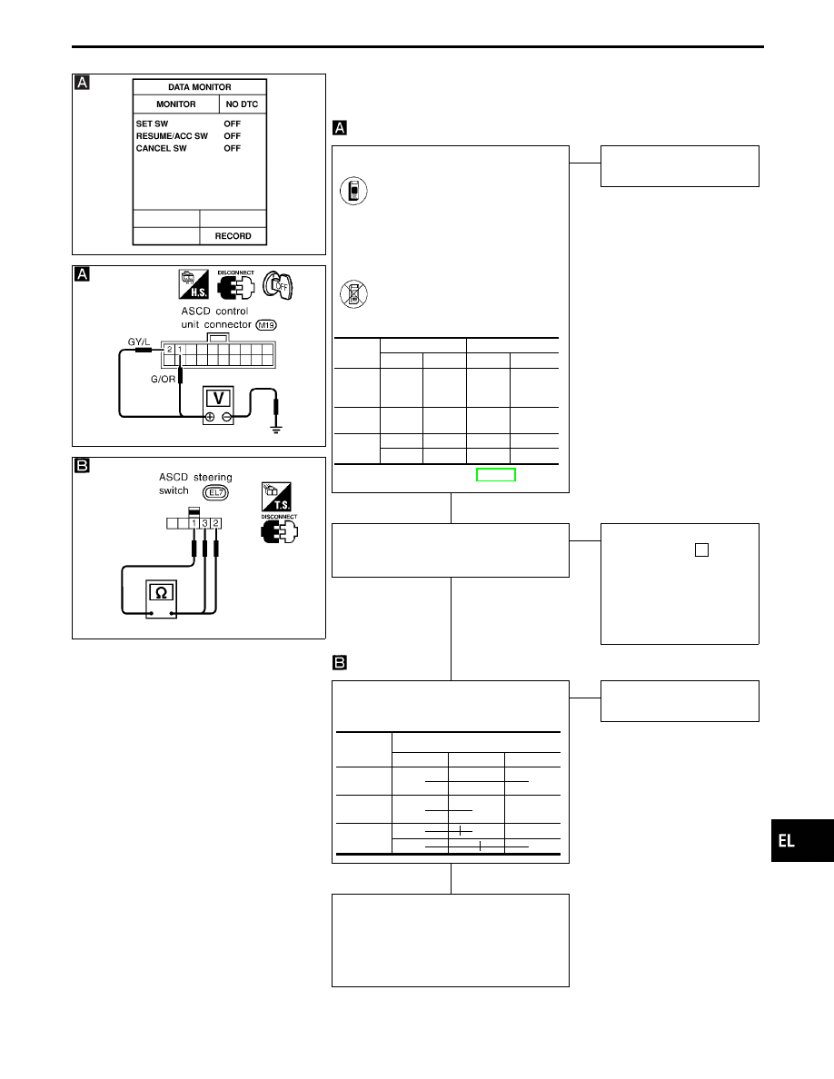
DIAGNOSTIC PROCEDURE 4

(ASCD STEERING SWITCH CHECK)

SEL760UA

SEL365V

CHECK ASCD STEERING SWITCH
INPUT.

See “SET SW”, “RESUME/ACC
SW” and “CANCEL SW” in “Data
monitor” mode.
SET SW, RESUME/ACC SW and
CANCEL SW
When switch is pressed: ON
When switch is released: OFF

-------------------------------------------------------------------------------------------------------------------------------------- OR --------------------------------------------------------------------------------------------------------------------------------------

1. Disconnect ASCD control unit

connector.

2. Check voltage between control

unit terminals and ground.

Refer to wiring diagram in EL-267.

NG

E

OK

ASCD steering switch is
OK.

CHECK POWER SUPPLY FOR ASCD
STEERING SWITCH.
Does horn work?

OK

E

NG

Check the following.

I

15A fuse (No.

64

,

located in the fuse, fus-
ible link and relay box)

I

Horn relay

I

Harness for open or
short between horn relay
and fuse

CHECK ASCD STEERING SWITCH.
Check continuity between terminals by
pushing each switch.

OK

E

NG

Replace ASCD steering
switch.

Check the following.

I

Harness for open or short between
ASCD steering switch and ASCD con-
trol unit

I

Harness for open or short between
ASCD steering switch and spiral cable

Terminal No.

Switch condition

!

@

Pressed Released

SET/

COAST

SW

q

2

Ground

12V

0V

RESUME/

ACC SW

q

1

Ground

12V

0V

CANCEL

SW

q

2

Ground

12V

0V

q

1

Ground

12V

0V

Switch

Terminal

q

1

q

3

q

2

SET/

COAST

q

q

RESUME/

ACCEL

q

q

CANCEL

q

E

q

q

E

q

GI

MA

EM

LC

EC

FE

AT

PD

FA

RA

BR

ST

RS

BT

HA

IDX

AUTOMATIC SPEED CONTROL DEVICE (ASCD)

Trouble Diagnoses (Cont’d)

H

H

H

EL-279

SEL516W

DIAGNOSTIC PROCEDURE 5

(VEHICLE SPEED SIGNAL CHECK)

SEL761UA

CHECK VEHICLE SPEED SIGNAL.

See “VHCL SPEED SE” in
“Data monitor” mode while driv-
ing.

-------------------------------------------------------------------------------------------------------------------------- OR --------------------------------------------------------------------------------------------------------------------------

1. Apply wheel chocks and jack

up drive wheel.

2. Disconnect ASCD control

unit connector.

3. Connect voltmeter between

control unit connector termi-
nal

q

7

and ground.

4. Slowly turn drive wheel.
5. Check deflection of voltme-

ter pointer.

Refer to wiring diagram in
EL-270.

NG

E

OK

Vehicle speed sensor is OK.

CHECK SPEEDOMETER OPERA-
TION.
Does speedometer operate normally?

Yes

E

No

Check speedometer and
vehicle speed sensor circuit.
Refer to EL-149.

Check harness for open or short
between ASCD control unit terminal

q

7

and combination meter terminal

q

18

.

AUTOMATIC SPEED CONTROL DEVICE (ASCD)

Trouble Diagnoses (Cont’d)

H

H

EL-280

MEL401GI

DIAGNOSTIC PROCEDURE 6

(ASCD PUMP CIRCUIT CHECK)

CHECK ASCD PUMP.
1. Disconnect ASCD pump connector.
2. Measure resistance between ASCD

pump terminals

q

1

and

q

2

,

q

3

,

q

4

.

Refer to wiring diagram in EL-269.

OK

E

NG

Replace ASCD pump.

Check harness for open or short between
ASCD pump and ASCD control unit.

If a self-diagnostic result has
already been accomplished,
check using the following table.

Terminals

Resistance

q

1

q

4

Approx. 3

q

2

Approx. 65

q

3

Approx. 65

CONSULT-II

self-diagnostic

result

Check circuit

ASCD control

unit terminal

ASCD pump

terminal

POWER SUP-
PLY-VALVE

q

8

q

1

VACUUM
PUMP

q

9

q

4

AIR VALVE

q

10

q

2

RELEASE
VALVE

q

14

q

3

GI

MA

EM

LC

EC

FE

AT

PD

FA

RA

BR

ST

RS

BT

HA

IDX

AUTOMATIC SPEED CONTROL DEVICE (ASCD)

Trouble Diagnoses (Cont’d)

H

EL-281

MEL402G

DIAGNOSTIC PROCEDURE 7

(ASCD ACTUATOR/PUMP CHECK)

MEL403G

MEL404GF

CHECK VACUUM HOSE.
Check vacuum hose (between ASCD
actuator and ASCD pump) for breakage,
cracks or fracture.

OK

E

NG

Repair or replace hose.

CHECK ASCD WIRE.
Check wire for improper installation, rust
formation or breaks.

OK

E

NG

Repair or replace wire.
Refer to “ASCD Wire
Adjustment” (EL-284).

CHECK ASCD ACTUATOR.
1. Disconnect vacuum hose from ASCD

actuator.

2. Apply −40 kPa (−0.41 kg/cm

2

, −5.8 psi)

vacuum to ASCD actuator with hand
vacuum pump.

ASCD wire should move to pull throttle
drum.
3. Wait 10 seconds and check for

decrease in vacuum pressure.

Vacuum pressure decrease:
Less than 2.7 kPa (0.028 kg/cm

2

, 0.39

psi)

OK

E

NG

Replace ASCD actuator.

CHECK ASCD PUMP.
1. Disconnect vacuum hose from ASCD

pump and ASCD pump connector.

2. If necessary remove ASCD pump.
3. Connect vacuum gauge to ASCD

pump.

4. Apply 12V direct current to ASCD

pump and check operation.

A vacuum pressure of at least −35 kPa
(−0.36 kg/cm

2

, −5.1 psi) should be gen-

erated.

OK

E

NG

Replace ASCD pump.

ASCD actuator/pump is OK.

12V direct current sup-

ply terminals

Operation

!

@

Air valve

q

1

q

2

Close

Release
valve

q

3

Close

Vacuum
motor

q

4

Operate

AUTOMATIC SPEED CONTROL DEVICE (ASCD)

Trouble Diagnoses (Cont’d)

H

H

H

H

EL-282


Content   ..  320  321  322  323   ..