Infiniti Q45 (FY33). Manual - part 320
SEF046TA
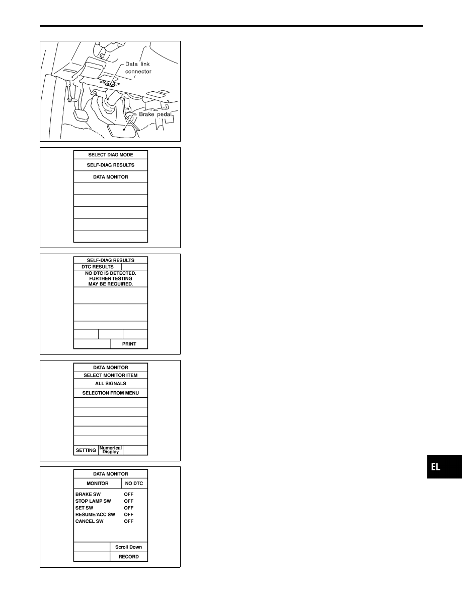
CONSULT-II
CONSULT-II INSPECTION PROCEDURE
1.
Turn ignition switch OFF.
2.
Connect “CONSULT-II” to data link connector.
SEL509W
3.
Turn ignition switch ON.
4.
Turn ASCD main switch ON.
5.
Touch START (on CONSULT-II display).
6.
Touch ASCD.
7.
Touch SELF-DIAG RESULTS.
SEL510W
I
Self-diagnostic results are shown on display.
Refer to table on the next page.
SEL511W
8.
Touch DATA MONITOR.
The items on the next page are available as data monitor
items.
SEL512W
I
Touch START.
I
Data monitor results are shown on display.
Refer to table on the next page.
For further information, read the CONSULT-II Operation
Manual.
GI
MA
EM
LC
EC
FE
AT
PD
FA
RA
BR
ST
RS
BT
HA
IDX
AUTOMATIC SPEED CONTROL DEVICE (ASCD)
EL-271