Infiniti Q45 (FY33). Manual - part 309


  Index      Infiniti     Infiniti Q45 (FY33) - service repair manual 2001 year


Search            copyright infringement  


Content   ..  307  308  309  310   ..


Infiniti Q45 (FY33). Manual - part 309


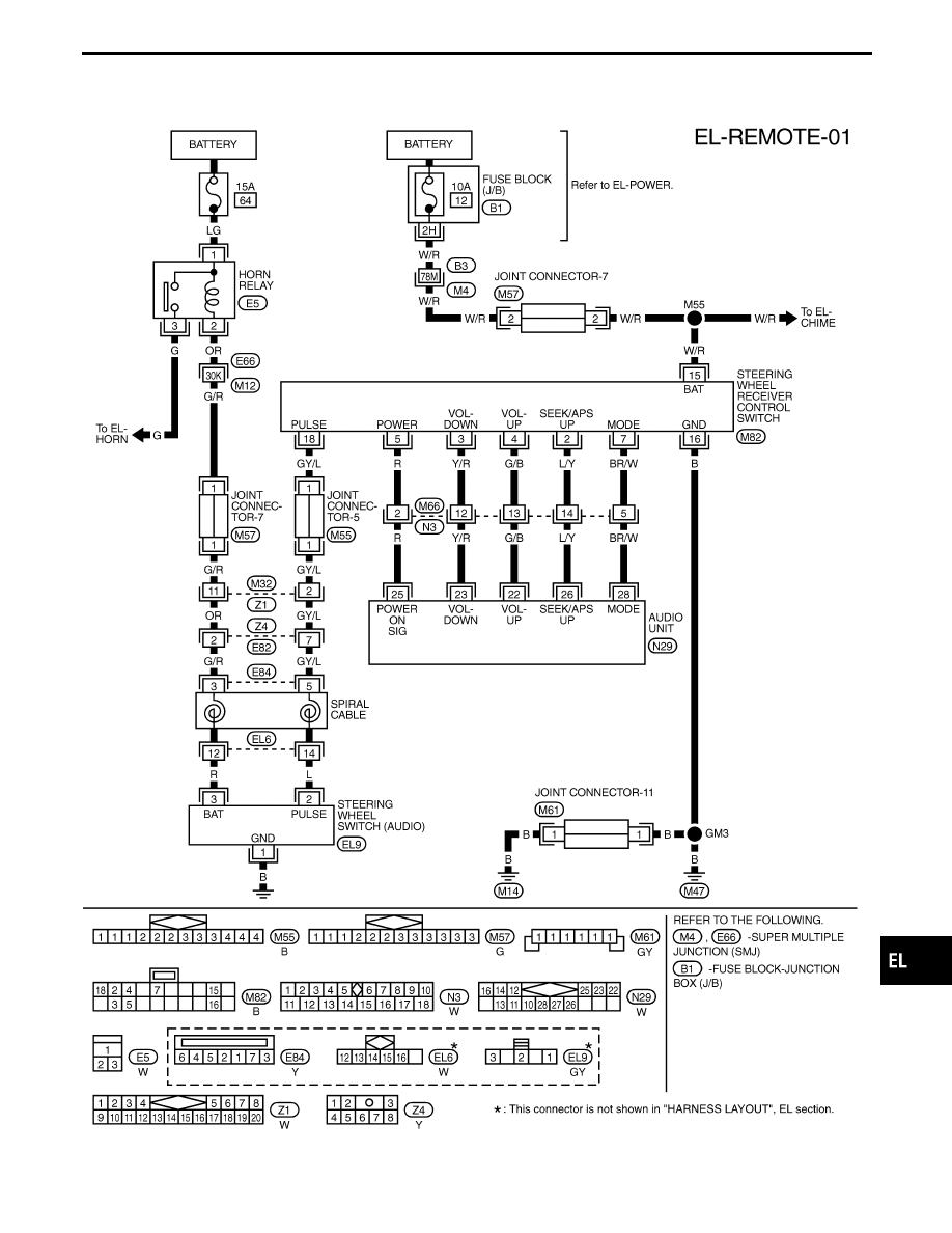
Wiring Diagram — REMOTE —

TEL750B

GI

MA

EM

LC

EC

FE

AT

PD

FA

RA

BR

ST

RS

BT

HA

IDX

AUDIO

EL-227

System Description

Power is supplied at all times

I

through 10A fuse [No.

28

, located in the fuse block (J/B)]

I

to power antenna timer and motor terminal

q

6

.

With the ignition switch in the ACC or ON position, power is supplied

I

through 10A fuse [No.

8

, located in the fuse block (J/B)]

I

to audio unit terminal

q

10

.

Ground is supplied to the power antenna timer and motor terminal

q

2

through body grounds

B22

and

B35

.

When the audio unit is turned to the ON position, battery positive voltage is supplied

I

through audio unit terminal

q

5

I

to power antenna timer and motor terminal

q

4

.

The antenna raises and is held in the extended position.
When the audio unit is turned to the OFF position, battery positive voltage is interrupted

I

from audio unit terminal

q

5

I

to power antenna timer and motor terminal

q

4

.

The antenna retracts.

AUDIO ANTENNA

EL-228

Wiring Diagram — P/ANT —

TEL112M

GI

MA

EM

LC

EC

FE

AT

PD

FA

RA

BR

ST

RS

BT

HA

IDX

AUDIO ANTENNA

EL-229

Trouble Diagnoses

POWER ANTENNA

Symptom

Possible causes

Repair order

Power antenna does not oper-
ate.

1. 10A fuse

2. Audio signal

3. Grounds

B22

and

B35

4. Power antenna timer and motor

1. Check 10A fuse [No.

28

, located in the fuse block (J/B)].

Verify that battery positive voltage is present at terminal

q

6

of power antenna timer and motor.

2. Turn ignition switch to ACC or ON and radio ON. Verify that

battery positive voltage is present at terminal

q

4

of power

antenna timer and motor.

3. Check grounds

B22

and

B35

.

4. Check power antenna timer and motor.

Location of Antenna

CEL427

CEL428

Antenna Rod Replacement

REMOVAL

1.

Remove antenna nut and antenna base.

CEL429

2.

Withdraw antenna rod while raising it by operating antenna
motor.

AUDIO ANTENNA

EL-230


Content   ..  307  308  309  310   ..