Infiniti Q45 (FY33). Manual - part 306
 

  Index      Infiniti     Infiniti Q45 (FY33) - service repair manual 2001 year


Search            copyright infringement  


Content   ..  304  305  306  307   ..


Infiniti Q45 (FY33). Manual - part 306


Filament Repair

REPAIR EQUIPMENT

1.

Conductive silver composition (Dupont No. 4817 or equivalent)

2.

Ruler 30 cm (11.8 in) long

3.

Drawing pen

4.

Heat gun

5.

Alcohol

6.

Cloth

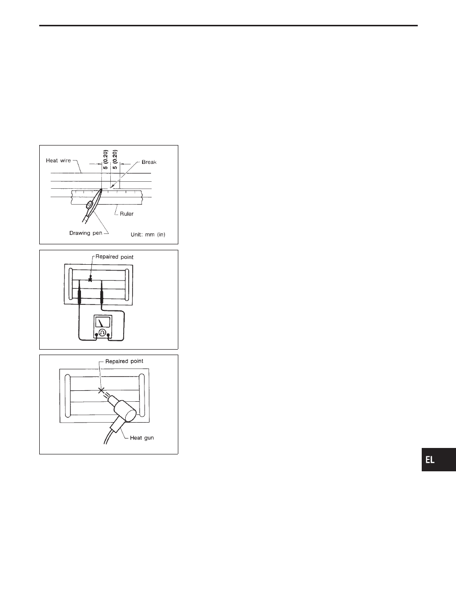
BE540

SEL012D

REPAIRING PROCEDURE

1.

Wipe broken heat wire and its surrounding area clean with a
cloth dampened in alcohol.

2.

Apply a small amount of conductive silver composition to tip of
drawing pen.

Shake silver composition container before use.
3.

Place ruler on glass along broken line. Deposit conductive sil-
ver composition on break with drawing pen. Slightly overlap
existing heat wire on both sides [preferably 5 mm (0.20 in)] of
the break.

4.

After repair has been completed, check repaired wire for con-
tinuity. This check should be conducted 10 minutes after silver
composition is deposited.

Do not touch repaired area while test is being conducted.

SEL013D

5.

Apply a constant stream of hot air directly to the repaired area
for approximately 20 minutes with a heat gun. A minimum dis-
tance of 3 cm (1.2 in) should be kept between repaired area
and hot air outlet. If a heat gun is not available, let the repaired
area dry for 24 hours.

GI

MA

EM

LC

EC

FE

AT

PD

FA

RA

BR

ST

RS

BT

HA

IDX

REAR WINDOW DEFOGGER

EL-215

System Description

BOSE SYSTEM

Refer to Owner’s Manual for audio system operating instructions.
Power is supplied at all times

I

through 15A fuse (No.

58

, located in the fuse, fusible link and relay box)

I

to audio unit terminal

q

6

.

I

to BOSE speaker amp. terminal

q

27

and

I

to audio amp. relay terminal

q

3

.

I

through 10A fuse [No.

12

, located in the fuse block (J/B)]

I

to CD auto changer terminal

q

52

.

With the ignition switch in the ACC or ON position, power is supplied

I

through 10A fuse [No.

8

, located in the fuse block (J/B)]

I

to audio unit terminal

q

10

and

I

to CD auto changer terminal

q

56

.

Ground is supplied through the case of the audio unit and BOSE speaker amp.
Ground is also supplied to CD auto changer terminal

q

55

through body grounds

B105

and

B118

.

When the audio unit is turned to the ON position, power is supplied

I

through audio unit terminal

q

12

I

to BOSE speaker amp. terminal

q

25

, and

I

to audio amp. relay terminal

q

1

.

The audio amp. relay is energized, power is supplied

I

through audio amp. relay terminal

q

5

I

to LH and RH rear speaker terminal

q

3

.

When the audio unit is turned to the ON position, audio signals are supplied

I

through terminals

q

13

,

q

14

,

q

15

,

q

16

,

q

1

,

q

2

,

q

3

and

q

4

of audio unit

I

to terminals

q

21

,

q

34

,

q

23

,

q

36

,

q

20

,

q

33

,

q

22

and

q

35

of the BOSE speaker amp.

I

through terminals

q

30

,

q

31

,

q

28

,

q

29

,

q

37

,

q

24

,

q

18

,

q

17

,

q

32

,

q

19

,

q

41

and

q

42

of the BOSE speaker amp.

I

to tweeters and the front and rear door speakers and rear speakers terminals

q

1

and

q

2

.

AUDIO

EL-216

Schematic

TEL200M

GI

MA

EM

LC

EC

FE

AT

PD

FA

RA

BR

ST

RS

BT

HA

IDX

AUDIO

EL-217

Wiring Diagram — AUDIO —

TEL105M

AUDIO

EL-218


Content   ..  304  305  306  307   ..