Infiniti Q45 (FY33). Manual - part 290


  Index      Infiniti     Infiniti Q45 (FY33) - service repair manual 2001 year


Search            copyright infringement  


Content   ..  288  289  290  291   ..


Infiniti Q45 (FY33). Manual - part 290


SEL368VA

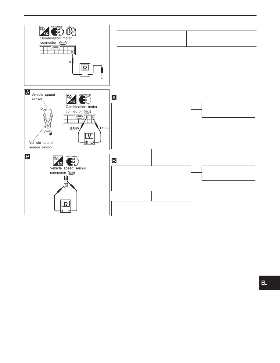
Ground circuit check

Terminals

Continuity

q

39

- Ground

Yes

SEL369VA

CEL914

INSPECTION/VEHICLE SPEED SENSOR

CHECK VEHICLE SPEED SENSOR
OUTPUT.
1. Remove vehicle speed sensor from

transmission.

2. Check voltage between combination

meter terminals

q

12

and

q

14

while quickly

turning speed sensor pinion.
Voltage: Approx. 0.5V

NG

E

OK

Vehicle speed sensor is
OK.

CHECK VEHICLE SPEED SENSOR.
Check resistance between vehicle speed
sensor terminals

q

1

and

q

2

.

Resistance: Approx. 250

OK

E

NG

Replace vehicle speed
sensor.

Check harness for open or short between
speedometer and vehicle speed sensor.

GI

MA

EM

LC

EC

FE

AT

PD

FA

RA

BR

ST

RS

BT

HA

IDX

METER AND GAUGES

Trouble Diagnoses (Cont’d)

H

H

EL-151

SEL370VA

INSPECTION/ENGINE REVOLUTION SIGNAL

CHECK ECM OUTPUT.
1. Start engine.
2. Check voltage between combination

meter terminal

q

13

and ground at idle

and 2,000 rpm.
Higher rpm = Higher voltage
Lower rpm = Lower voltage
Voltage should change with rpm.

NG

E

OK

Engine revolution signal is
OK.

Check the following.

I

Harness for open or short between ECM
and combination meter

SEL632VB

SEL372VD

INSPECTION/FUEL LEVEL SENSOR UNIT

CHECK GROUND CIRCUIT FOR FUEL
LEVEL SENSOR UNIT.
Check harness continuity between fuel
level sensor unit terminal

q

4

and ground.

Continuity should exist.

OK

E

NG

Check harness for open or
short between ECM and
fuel level sensor unit.

CHECK FUEL LEVEL SENSOR UNIT.
Refer to “FUEL LEVEL SENSOR UNIT
CHECK” (EL-154).

OK

E

NG

Repair or replace.
Refer to FE section.
(“FUEL SYSTEM”)

CHECK HARNESS FOR OPEN OR
SHORT.
1. Disconnect combination meter connec-

tor and fuel level sensor unit connector.

2. Check continuity between combination

meter terminal

q

8

and fuel level sensor

unit terminal

q

5

.

Continuity should exist.
3. Check continuity between combination

meter terminal

q

8

and ground.

Continuity should not exist.

OK

E

NG

Repair harness or connec-
tor.

Fuel level sensor unit is OK.

METER AND GAUGES

Trouble Diagnoses (Cont’d)

H

H

H

H

EL-152

SEL373VA

INSPECTION/THERMAL TRANSMITTER

CHECK THERMAL TRANSMITTER.
Refer to “THERMAL TRANSMITTER
CHECK” (EL-154).

OK

E

NG

Repair or replace.

CHECK HARNESS FOR OPEN OR
SHORT.
1. Disconnect combination meter connec-

tor and thermal transmitter connector.

2. Check continuity between combination

meter terminal

q

7

and thermal transmit-

ter terminal

q

1

.

Continuity should exist.
3. Check continuity between combination

meter terminal

q

7

and ground.

Continuity should not exist.

OK

E

NG

Repair harness or connec-
tor.

Thermal transmitter is OK.

Electrical Components Inspection

METER/GAUGE RESISTANCE CHECK

1.

Disconnect FPC connector. Refer to “Flexible Print Circuit
(FPC)” (EL-148).

2.

Check resistance between installation screws of meter/gauge
after removing meter/gauge.

Screws

Resistance

Tachometer

Fuel/Temp. gauge

A - C

A - C

Approx. 70 - Approx. 140

B - D

B - C

Approx. 90 - Approx. 170

CEL915

GI

MA

EM

LC

EC

FE

AT

PD

FA

RA

BR

ST

RS

BT

HA

IDX

METER AND GAUGES

Trouble Diagnoses (Cont’d)

H

H

EL-153

SEL064X

FUEL LEVEL SENSOR UNIT CHECK

I

For removal, refer to FE section “FUEL SYSTEM”.

Check the resistance between terminals

q

5

and

q

4

.

Ohmmeter

Float position

mm (in)

Resistance value

(+)

(−)

q

5

q

4

*3

Full

70 (2.76)

Approx. 4 - 6

*2

1/2

189 (7.44)

31 - 34

*1

Empty

308 (12.13)

80 - 83

*1 and *3: When float rod is in contact with stopper.

MEL424F

THERMAL TRANSMITTER CHECK

Check the resistance between the terminals of thermal transmitter
and body ground.

Water temperature

Resistance

60°C (140°F)

Approx. 170 - 210

100°C (212°F)

Approx. 47 - 53

MEL425F

OIL PRESSURE SWITCH CHECK

Oil pressure

kPa (kg/cm

2

, psi)

Continuity

Engine start

More than 20 - 29

(0.2 - 0.3, 3 - 4)

NO

Engine stop

Less than 20 - 29

(0.2 - 0.3, 3 - 4)

YES

Check the continuity between the terminals of oil pressure switch
and body ground.

CEL219

VEHICLE SPEED SENSOR SIGNAL CHECK

1.

Remove vehicle speed sensor from transmission.

2.

Turn vehicle speed sensor pinion quickly with fingers and mea-
sure voltage across

q

2

and

q

1

.

CEL520

DIODE CHECK

I

Check continuity using an ohmmeter.

I

Diode is functioning properly if test results are as shown in the
figure at left.

NOTE: Specification may vary depending on the type of tester.

Before performing this inspection, be sure to refer to
the instruction manual for the tester to be used.

METER AND GAUGES

Electrical Components Inspection (Cont’d)

EL-154


Content   ..  288  289  290  291   ..