Infiniti Q45 (FY33). Manual - part 274


  Index      Infiniti     Infiniti Q45 (FY33) - service repair manual 2001 year


Search            copyright infringement  


Content   ..  272  273  274  275   ..


Infiniti Q45 (FY33). Manual - part 274


Bulb Replacement/Xenon Type

CAUTION:

I

After replacing a new xenon bulb, be sure to make aiming
adjustments.

I

Hold only the plastic base when handling the bulb. Never
touch the glass envelope.

I

Do not leave headlamp reflector without bulb for a long
period of time. Dust, moisture, smoke, etc. entering head-
lamp body may affect the performance of the headlamp.
Remove headlamp bulb from the headlamp reflector just
before a replacement bulb is installed.

1.

Disconnect negative battery cable.

2.

Disconnect headlamp connector.

3.

Remove headlamp assembly.

WARNING:

Never service a xenon headlamp with wet hands.

SEL803V

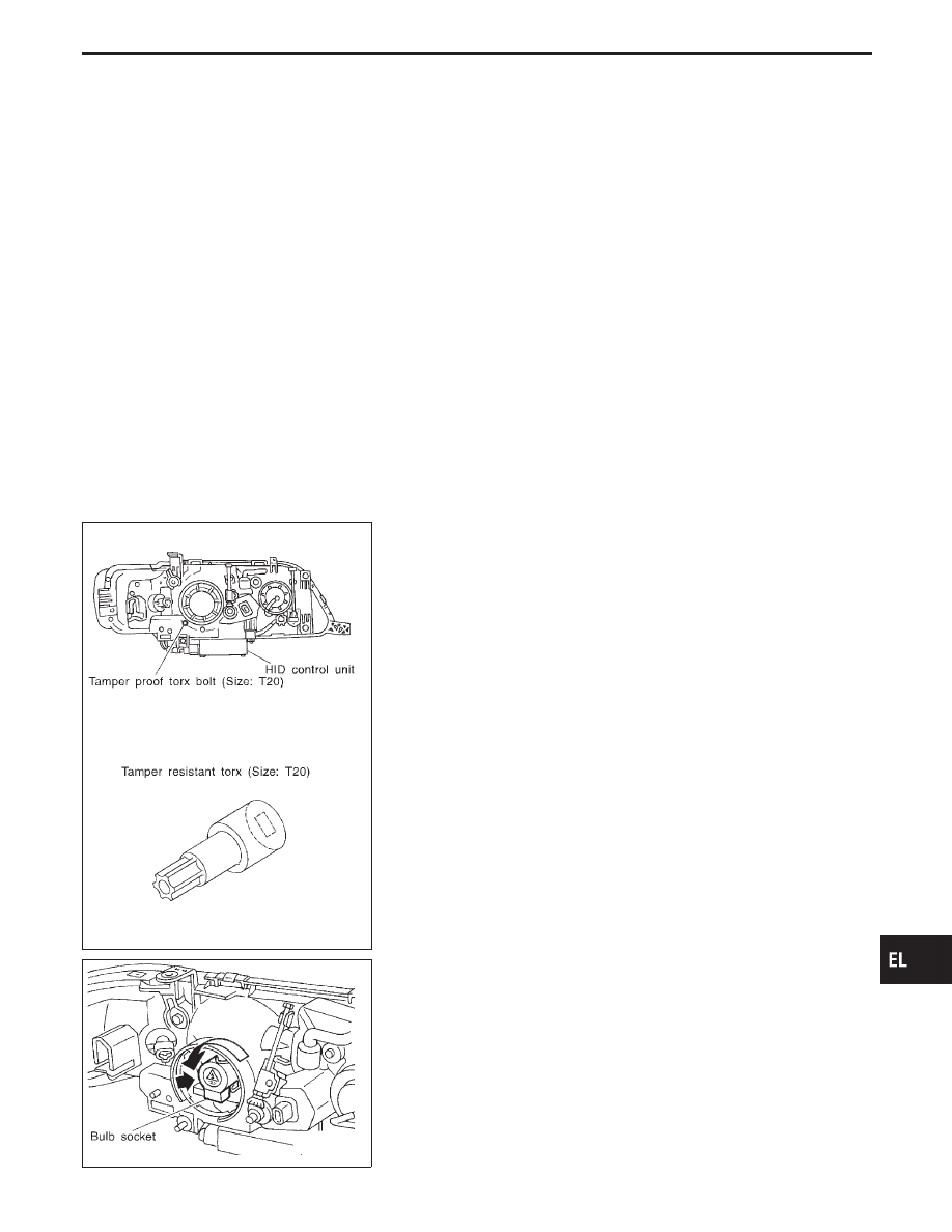
XENON BULB (LOW BEAM)

1.

Remove tamper proof torx bolt (size: T20), then remove head-
lamp seal cover.

SEL804V

2.

Turn bulb socket counterclockwise with keep pushing, then
remove it.

GI

MA

EM

LC

EC

FE

AT

PD

FA

RA

BR

ST

RS

BT

HA

IDX

HEADLAMP (FOR U.S.A.) — XENON TYPE —

EL-87

SEL805V

3.

Release retaining pin.

4.

Remove the xenon bulb.

5.

Install in the reverse order of removal.

CAUTION:

I

When disposing of the xenon bulb, do not break it; always
dispose of it as is.

I

Make sure to install the bulb securely; if the xenon bulb is
improperly installed in its socket, high-tension current
leaks occur. This may lead to a melted bulb and/or bulb
socket.

SEL806V

HIGH BEAM

1.

Remove headlamp seal cover by turning it counterclockwise.

2.

Disconnect bulb connector.

3.

Release retaining pin.

4.

Remove the bulb.

5.

Install in the reverse order of removal.

SEL829V

Aiming Adjustment/Xenon Type

LOW BEAM

1.

Turn headlamp low beam on.

2.

Use adjusting screw to perform aiming adjustment.

I

First tighten the adjusting screw all the way and then
make adjustment by loosening the screw.

HEADLAMP (FOR U.S.A.) — XENON TYPE —

Bulb Replacement/Xenon Type
(Cont’d)

EL-88

SEL957V

SEL466V

CAUTION:

Be sure aiming switch is set to “0” when performing aiming
adjustment.

GI

MA

EM

LC

EC

FE

AT

PD

FA

RA

BR

ST

RS

BT

HA

IDX

HEADLAMP (FOR U.S.A.) — XENON TYPE —

Aiming Adjustment/Xenon Type (Cont’d)

EL-89

Component Parts and Harness Connector
Location

SEL142Y

Daytime Light System/System Description

The headlamp system for Canada vehicles contains a daytime light control unit that activates the high beam
headlamps at approximately half illumination whenever the engine is running. If the parking brake is applied
before the engine is started the daytime lights will not be illuminated. The daytime lights will illuminate once
the parking brake is released. Thereafter, the daytime lights will continue to operate when the parking brake
is applied.
Power is supplied at all times

I

to headlamp relay terminal

q

1

, and

I

through 15A fuse (No.

53

, located in the fuse and fusible link box)

I

to headlamp relay terminal

q

5

, and

I

through 15A fuse (No.

54

, located in the fuse and fusible link box)

I

to headlamp relay terminal

q

7

.

With the ignition switch in the ON or START position, power is supplied

I

through 7.5A fuse [No.

20

, located in the fuse block (J/B)]

I

to daytime light control unit terminal

q

3

.

With the ignition switch in the START position, power is supplied

I

through 7.5A fuse [No.

34

, located in the fuse block (J/B)]

I

to daytime light control unit terminal

q

2

.

Ground is supplied to daytime light control unit terminal

q

16

through body grounds

E22

and

E36

.

HEADLAMP SWITCH OPERATION

When the lighting switch is turned to 2ND or PASS (“C”) positions, ground is supplied

I

to headlamp relay terminal

q

2

I

from the lighting switch terminal

q

12

.

Headlamp relay is then energized, and power is supplied

I

from the headlamp relay terminal

q

6

I

to combination meter terminal

q

22

for the HIGH BEAM indicator and

I

through daytime light control unit terminals

q

5

and

q

6

I

to terminal

q

2

of the LH headlamp.

Power is also supplied

I

from the headlamp relay terminal

q

3

I

through daytime light control unit terminals

q

4

and

q

7

I

to terminal

q

2

of the RH headlamp.

HEADLAMP (FOR CANADA) — CONVENTIONAL TYPE —

EL-90


Content   ..  272  273  274  275   ..