Infiniti Q45 (FY33). Manual - part 263
Trouble Diagnoses with
Battery/Starting/Charging System Tester
NOTE:
To ensure a complete and thorough diagnosis, the battery,
starter and alternator test segments must be done as a set
from start to finish.
SEL408X
1.
Turn off all loads on the vehicle electrical system.
2.
Perform battery test with Battery/Starting/Charging system
tester. Refer to EL-38.
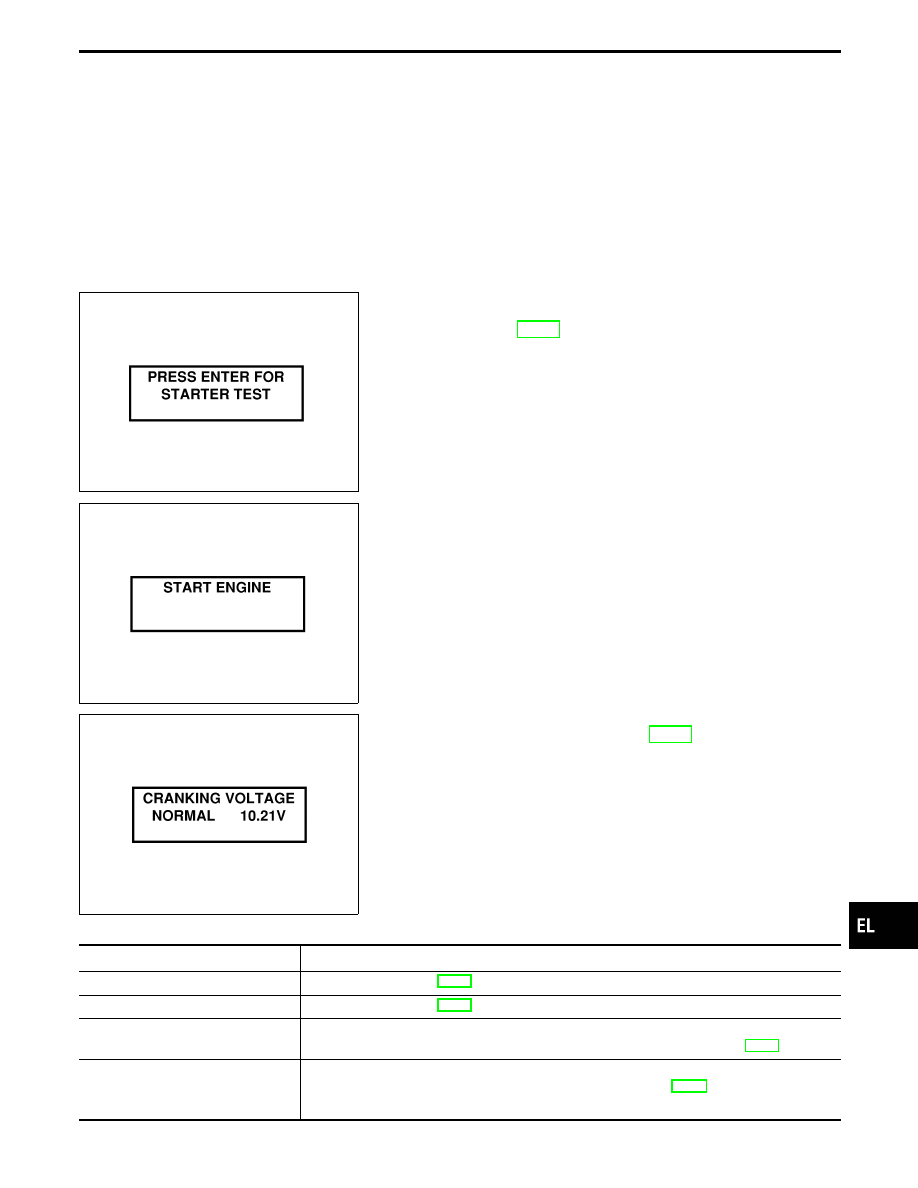
3.
Press “ENTER” to begin the starting system test.
SEL409X
4.
Start the engine.
SEL410X
5.
Diagnosis result is displayed on the tester. Refer to “DIAG-
NOSTIC RESULT ITEM CHART”, EL-43.
NOTE:
I
If the starter performs normally but the engine does not
start, perform engine diagnosis.
I
For intermittent “NO CRANK” or “NO STARTER OPERA-
TION” incidents, go to DIAGNOSTIC PROCEDURE 2.
DIAGNOSTIC RESULT ITEM CHART
Diagnostic item
Service procedure
CRANKING VOLTAGE NORMAL
Go to “WORK FLOW”, EL-44.
CRANKING VOLTAGE LOW
Go to “WORK FLOW”, EL-44.
CHARGE BATTERY
Perform the slow battery charging procedure. (Initial rate of charge is 10A for 12 hours.) Per-
form battery test again with Battery/Starting/Charging system tester. Refer to EL-38.
REPLACE BATTERY
Before replacing battery, clean the battery cable clamps and battery posts. Perform battery
test again with Battery/Starting/Charging system tester. Refer to EL-38. If second test result
is “REPLACE BATTERY”, then do so. Perform battery test again to confirm repair.
GI
MA
EM
LC
EC
FE
AT
PD
FA
RA
BR
ST
RS
BT
HA
IDX
STARTING SYSTEM
EL-43