Infiniti Q45 (FY33). Manual - part 237


  Index      Infiniti     Infiniti Q45 (FY33) - service repair manual 2001 year


Search            copyright infringement  


Content   ..  235  236  237  238   ..


Infiniti Q45 (FY33). Manual - part 237


SEC059C

SEF239Y

9) Select “PURG VOL C/V P1444” of “EVAPORATIVE

SYSTEM” in “DTC WORK SUPPORT” mode with CON-
SULT-II.

10) Touch “START”.

If “COMPLETED” is displayed on CONSULT-II screen,
go to step 12).

11) When the following conditions are met, “TESTING” will

be displayed on the CONSULT-II screen. Maintain the
conditions continuously until “TESTING” changes to
“COMPLETED”. (It will take at least 20 seconds.)
CMPS-RPM (POS): 900 - 6,300 rpm
Vehicle speed: 36 - 120 km/h (22 - 75 MPH)
B/FUEL SCHDL: 2 - 4.8 msec
Selector lever: Suitable position

If “TESTING” is not displayed after 5 minutes, retry
from step 3).
12) Make sure that “OK” is displayed after touching “SELF-

DIAG RESULTS”. If “NG” is displayed, refer to
“TROUBLE DIAGNOSIS FOR DTC P1444”, EC-444.

13) Select “VC CUT/V BP/V P1491” of “EVAPORATIVE

SYSTEM” in “DTC WORK SUPPORT” mode with CON-
SULT-II.

14) Touch “START”.
15) When the following conditions are met, “TESTING” will

be displayed on the CONSULT-II screen. Maintain the
conditions continuously until “TESTING” changes to
“COMPLETED”. (It will take at least 30 seconds.)
CMPS-RPM (POS): 900 - 6,300 rpm
Vehicle speed: 36 - 120 km/h (22 - 75 MPH)
B/FUEL SCHDL: 0.5 - 4.5 msec
Selector lever: Suitable position

If “TESTING” is not displayed after 5 minutes, retry
from step 3).
16) Make sure that “OK” is displayed after touching “SELF-

DIAG RESULTS”. If “NG” is displayed, refer to “DIAG-
NOSTIC PROCEDURE”, EC-478.

SEF530Q

------------------------------------------------------------------------------------------------------------------------------------------------------------------------------------------------------------------------------------------------------ OR ------------------------------------------------------------------------------------------------------------------------------------------------------------------------------------------------------------------------------------------------------

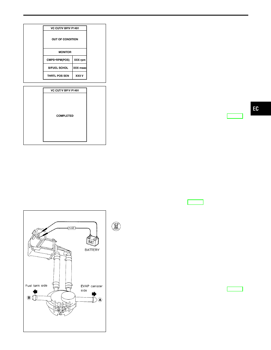
OVERALL FUNCTION CHECK

1) Remove vacuum cut valve and vacuum cut valve

bypass valve as an assembly.

2) Apply vacuum to port

q

A

and check that there is no

suction from port

q

B

.

3) Apply vacuum to port

q

B

and check that there is suction

from port

q

A

.

4) Blow air in port

q

B

and check that there is a resistance

to flow out of port

q

A

.

5) Supply battery voltage to the terminal.
6) Blow air in port

q

A

and check that air flows freely out of

port

q

B

.

7) Blow air in port

q

B

and check that air flows freely out of

port

q

A

.

8) If NG, go to “DIAGNOSTIC PROCEDURE”, EC-478.

GI

MA

EM

LC

FE

AT

PD

FA

RA

BR

ST

RS

BT

HA

EL

IDX

TROUBLE DIAGNOSIS FOR DTC P1491

Vacuum Cut Valve Bypass Valve (Cont’d)

EC-477

SEC057C

SEF530Q

SEF623U

SEF427U

DIAGNOSTIC PROCEDURE

INSPECTION START

CHECK COMPONENT.
1. Remove vacuum cut valve and vacuum

cut valve bypass valve as an assembly.

2. Apply vacuum to port

q

A

and check that

there is no suction from port

q

B

.

3. Apply vacuum to port

q

B

and check that

there is suction from port

q

A

.

4. Blow air in port

q

B

and check that there

is a resistance to flow out of port

q

A

.

5. Select “VC/V BYPASS/V” in

“ACTIVE TEST” mode with CON-
SULT-II and touch “ON”.

-------------------------------------------------------------------------------------------------------------------------------------- OR --------------------------------------------------------------------------------------------------------------------------------------

5. Supply battery voltage to the ter-

minal.

6. Blow air in port

q

A

and check that air

flows freely out of port

q

B

.

7. Blow air in port

q

B

and check that air

flows freely out of port

q

A

.

NG

E

OK

Check the following.

I

EVAP purge line between
EVAP canister and fuel
tank for clogging or dis-
connection.

I

EVAP canister Refer to
EC-26.

I

EVAP purge port of fuel
tank for clogging

If NG, repair or replace.

OK

Go to

below.

Check bypass hoses for clogging.

OK

E

NG

Repair or replace hoses.

CHECK COMPONENT
(Vacuum cut valve, vacuum cut valve
bypass valve).
Refer to “COMPONENT INSPECTION” on
next page.

OK

E

NG

Replace malfunctioning
parts.

CHECK COMPONENT
(EVAP control system pressure sensor).
1. Check for disconnection of hose con-

nected to the sensor.

2. Check sensor harness connector for

water.
Water should not exist.
If OK, go to the following step.

3. Check EVAP control system pressure

sensor.

Refer to “COMPONENT INSPECTION” on
next page.

OK

E

NG

Repair or replace harness,
connectors and/or replace
EVAP control system pres-
sure sensor.

CHECK COMPONENT
(EVAP canister vent control valve).
Refer to “COMPONENT INSPECTION”,
EC-480.

OK

E

NG

Repair or replace.

Perform “TROUBLE DIAGNOSIS FOR
INTERMITTENT INCIDENT”, EC-117.

INSPECTION END

TROUBLE DIAGNOSIS FOR DTC P1491

Vacuum Cut Valve Bypass Valve (Cont’d)

H

H

H

H

H

H

H

H

EC-478

SEC057C

SEF351Q

COMPONENT INSPECTION

Vacuum cut valve bypass valve

Check air passage continuity.

Perform “VC/V BYPASS/V” in “ACTIVE TEST” mode.

Condition

VC/V BYPASS/V

Air passage continuity

between

q

A

and

q

B

ON

Yes

OFF

No

------------------------------------------------------------------------------------------------------------------------------------------------------------------------------------------------------------------------------------------------------ OR ------------------------------------------------------------------------------------------------------------------------------------------------------------------------------------------------------------------------------------------------------

Condition

Air passage continuity

between

q

A

and

q

B

12V direct current supply between terminals

Yes

No supply

No

If NG or operation takes more than 1 second, replace vacuum cut
valve bypass valve.

SEF379Q

Vacuum cut valve

Check vacuum cut valve as follows:
1.

Plug port

q

C

and

q

D

with fingers.

2.

Apply vacuum to port

q

A

and check that there is no suction

from port

q

B

.

3.

Apply vacuum to port

q

B

and check that there is suction from

port

q

A

.

4.

Blow air in port

q

B

and check that there is a resistance to flow

out of port

q

A

.

5.

Open port

q

C

and

q

D

.

6.

Blow air in port

q

A

check that air flows freely out of port

q

C

.

7.

Blow air in port

q

B

check that air flows freely out of port

q

D

.

SEF357W

SEF799W

EVAP control system pressure sensor

1.

Remove EVAP control system pressure sensor with its har-
ness connector connected.

2.

Remove hose from EVAP control system pressure sensor.

3.

Turn ignition switch “ON”.

4.

Use pump to apply vacuum and pressure to EVAP control
system pressure sensor as shown in figure.

5.

Check output voltage between ECM terminal

q

92

and ground.

Pressure (Relative to atmospheric pressure)

Voltage (V)

0 kPa (0 mmHg, 0 inHg)

3.0 - 3.6

−9.3 kPa (−70 mmHg, −2.76 inHg)

0.4 - 0.6

CAUTION:

I

Always calibrate the vacuum pump gauge when using it.

I

Do not apply below −20 kPa (−150 mmHg, −5.91 inHg) or
over 20 kPa (150 mmHg, 5.91 inHg) of pressure.

6.

If NG, replace EVAP control system pressure sensor.

I

Never apply force to the air hole protector of the sensor,
if equipped.

I

Discard any EVAP control system pressure sensor which
has been dropped from a height of more than 0.5 m (19.7
in) onto a hard surface such as a concrete floor; use a new
one.

GI

MA

EM

LC

FE

AT

PD

FA

RA

BR

ST

RS

BT

HA

EL

IDX

TROUBLE DIAGNOSIS FOR DTC P1491

Vacuum Cut Valve Bypass Valve (Cont’d)

EC-479

SEC050C

AEC783A

EVAP canister vent control valve

Check air passage continuity.

Perform “VENT CONTROL/V” in “ACTIVE TEST” mode with
CONSULT-II.

Condition

VENT CONTROL/V

Air passage continuity

between

q

A

and

q

B

ON

No

OFF

Yes

------------------------------------------------------------------------------------------------------------------------------------------------------------------------------------------------------------------------------------------------------ OR ------------------------------------------------------------------------------------------------------------------------------------------------------------------------------------------------------------------------------------------------------

Condition

Air passage continuity

between

q

A

and

q

B

12V direct current supply between ter-
minals

q

1

and

q

2

No

No supply

Yes

If NG or operation takes more than 1 second, clean valve using air
blower or replace as necessary.
If the portion

q

B

is rusted, replace EVAP canister vent control

valve.
Make sure new O-ring is installed properly.

TROUBLE DIAGNOSIS FOR DTC P1491

Vacuum Cut Valve Bypass Valve (Cont’d)

EC-480


Content   ..  235  236  237  238   ..