Infiniti Q45 (FY33). Manual - part 235
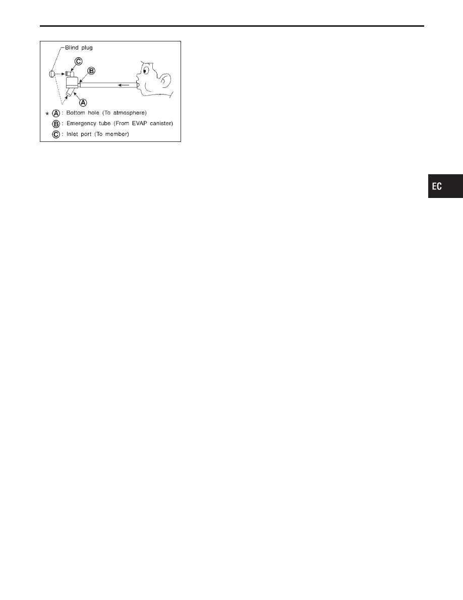
SEF829T
Water separator
1.
Check visually for insect nests in the water separator air inlet.
2.
Check visually for cracks or flaws in the appearance.
3.
Check visually for cracks or flaws in the hose.
4.
Check that
q
A
and
q
C
are not clogged by blowing air into
q
B
with
q
A
, and then
q
C
plugged.
5.
In case of NG in items 2 - 4, replace the parts.
NOTE:
Do not disassemble water separator.
GI
MA
EM
LC
FE
AT
PD
FA
RA
BR
ST
RS
BT
HA
EL
IDX
TROUBLE DIAGNOSIS FOR DTC P1448
Evaporative Emission (EVAP) Canister Vent
Control Valve (Open) (Cont’d)
EC-469