Infiniti Q45 (FY33). Manual - part 201


  Index      Infiniti     Infiniti Q45 (FY33) - service repair manual 2001 year


Search            copyright infringement  


Content   ..  199  200  201  202   ..


Infiniti Q45 (FY33). Manual - part 201


SEC050C

AEC783A

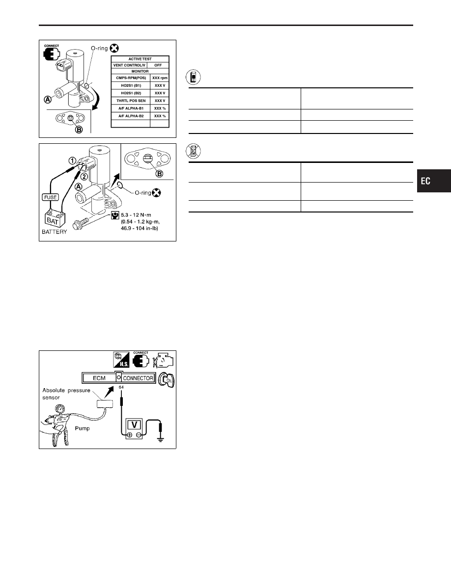
EVAP canister vent control valve

Check air passage continuity.

Perform “VENT CONTROL/V” in “ACTIVE TEST” mode.

Condition

Air passage continuity

between

q

A

and

q

B

ON

No

OFF

Yes

------------------------------------------------------------------------------------------------------------------------------------------------------------------------------------------------------------------------------------------------------ OR ------------------------------------------------------------------------------------------------------------------------------------------------------------------------------------------------------------------------------------------------------

Condition

Air passage continuity

between

q

A

and

q

B

12V direct current supply between ter-
minals

q

1

and

q

2

No

No supply

Yes

If NG or operation takes more than 1 second, clean valve using air
blower or replace as necessary.
If portion

q

B

is rusted, replace control valve.

Make sure new O-ring is installed properly.

SEF747W

Absolute pressure sensor

1.

Remove absolute pressure sensor with its harness connector
connected.

2.

Remove hose from absolute pressure sensor.

3.

Turn ignition switch “ON” and check output voltage between
ECM terminal

q

64

and engine ground.

The voltage should be 3.2 to 4.8V.

4.

Use pump to apply vacuum of −26.7 kPa (−200 mmHg, −7.87
inHg) to absolute pressure sensor as shown in figure and
check the output voltage.
The voltage should be 1.0 to 1.4V lower than the value
measured in step 3.

CAUTION:

I

Always calibrate the vacuum pump gauge when using it.

I

Do not apply vacuum below −93.3 kPa (−700 mmHg,
−27.56 inHg) or pressure over 101.3 kPa (760 mmHg, 29.92
inHg).

5.

If NG, replace absolute pressure sensor.

GI

MA

EM

LC

FE

AT

PD

FA

RA

BR

ST

RS

BT

HA

EL

IDX

TROUBLE DIAGNOSIS FOR DTC P0455

Evaporative Emission (EVAP) Control System
(Gross Leak) (Cont’d)

EC-333

SEF767X

SEF768X

MEC488B

MAP/BARO switch solenoid valve

1. Start engine and warm it up to normal operating tem-

perature.

2. Perform “MAP/BARO SW/V” in “ACTIVE TEST” mode

with CONSULT-II.

3. Check the following.

I

Condition: At idle under no-load.

I

CONSULT-II display

MAP/BARO SW/V

ABSOL PRES/SE (Voltage)

BARO

More than 2.6V

MAP

Less than the voltage at BARO

I

Time for voltage to change

MAP/BARO SW/V

Required time to switch

BARO to MAP

Less than 1 second

MAP to BARO

4. If NG, check solenoid valve as shown below.

------------------------------------------------------------------------------------------------------------------------------------------------------------------------------------------------------------------------------------------------------ OR ------------------------------------------------------------------------------------------------------------------------------------------------------------------------------------------------------------------------------------------------------

1. Remove MAP/BARO switch solenoid valve.
2. Check air passage continuity.

Condition

Air passage

continuity

between

q

A

and

q

B

Air passage

continuity

between

q

A

and

q

C

12V direct current supply
between

terminals

q

1

and

q

2

Yes

No

No supply

No

Yes

3. If NG or operation takes more than 1 second, replace

solenoid valve.

SEF405UA

Fuel tank temperature sensor

Check resistance by heating with hot water or heat gun as shown
in the figure.

Temperature °C (°F)

Resistance k

20 (68)

2.3 - 2.7

50 (122)

0.79 - 0.90

If NG, replace fuel tank temperature sensor.

TROUBLE DIAGNOSIS FOR DTC P0455

Evaporative Emission (EVAP) Control System
(Gross Leak) (Cont’d)

EC-334

SEF061T

Vehicle Speed Sensor (VSS)

COMPONENT DESCRIPTION

The vehicle speed sensor is installed in the transmission. It con-
tains a pulse generator which provides a vehicle speed signal to
the speedometer. The speedometer then sends a signal to the
ECM.

ECM TERMINALS AND REFERENCE VALUE

Specification data are reference values, and are measured between each terminal and ground.

CAUTION:

Do not use ECM ground terminals when measuring voltage. Doing so may result in damage to the
ECM’s transistor. Use a ground other than ECM terminals such as the body ground.

TER-

MINAL

NO.

WIRE

COLOR

ITEM

CONDITION

DATA

(DC voltage)

68

P/L

Vehicle speed sensor

Engine is running.

Lift up drive wheels and run engine at idle in
“D” position.

Approximately 5.2V

SEF542T

ON BOARD DIAGNOSIS LOGIC

Diagnostic Trouble

Code No.

Malfunction is detected when ....

Check Items

(Possible Cause)

P0500
0104

I

The almost 0 km/h (0 MPH) signal from the vehicle
speed sensor is sent to ECM even when the vehicle
is driving.

I

Harness or connector
(The vehicle speed sensor circuit is open or
shorted.)

I

Vehicle speed sensor

GI

MA

EM

LC

FE

AT

PD

FA

RA

BR

ST

RS

BT

HA

EL

IDX

TROUBLE DIAGNOSIS FOR DTC P0500

EC-335

SEF274Y

DIAGNOSTIC TROUBLE CODE CONFIRMATION
PROCEDURE

CAUTION:

Always drive vehicle at a safe speed.
NOTE:
If “DIAGNOSTIC TROUBLE CODE CONFIRMATION PROCE-
DURE” has been previously conducted, always turn ignition
switch “OFF” and wait at least 5 seconds before conducting
the next test.
TESTING CONDITION:
Step 1 and 2 may be conducted with the drive wheels lifted in
the shop or by driving the vehicle. If a road test is expected
to be easier, it is unnecessary to lift the vehicle.

1) Start engine.
2) Read vehicle speed sensor signal in “DATA MONITOR”

mode with CONSULT-II. The vehicle speed on CON-
SULT-II should exceed 10 km/h (6 MPH) when rotating
wheels with suitable gear position.
If NG, go to “DIAGNOSTIC PROCEDURE”, EC-339.
If OK, go to following step.

3) Select “DATA MONITOR” mode with CONSULT-II.
4) Warm engine up to normal operating temperature.
5) Maintain the following conditions for at least 10 con-

secutive seconds with TCS switch “OFF”.
CMPS-RPM (POS): 1,300 - 2,250 rpm
COOLAN TEMP/S: More than 70°C (158°F)
B/FUEL SCHDL: 2.0 - 3.5 msec
Selector lever: Suitable position
PW/ST SIGNAL: OFF

6) If 1st trip DTC is detected, go to “DIAGNOSTIC

PROCEDURE”, EC-339.

TROUBLE DIAGNOSIS FOR DTC P0500

Vehicle Speed Sensor (VSS) (Cont’d)

EC-336


Content   ..  199  200  201  202   ..