Infiniti Q45 (FY33). Manual - part 191
DIAGNOSTIC PROCEDURE
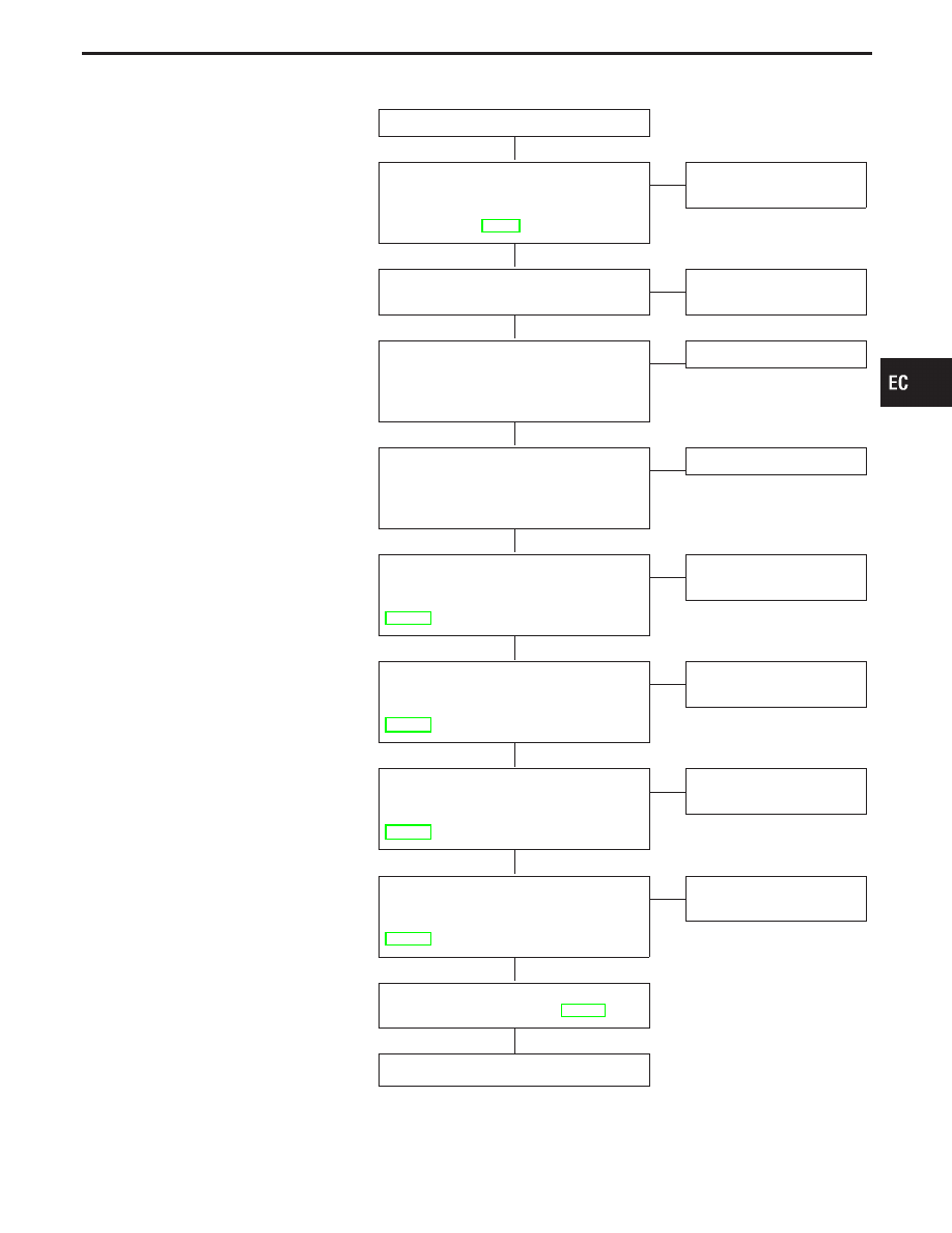
INSPECTION START
CHECK HOSE.
Check vacuum hose for clogging and
improper connection. Refer to “Vacuum
Hose Drawing”, EC-19.
OK
E
NG
Repair or replace vacuum
hose.
CHECK EXHAUST SYSTEM.
Check exhaust system for collapse.
OK
E
NG
Repair or replace exhaust
system.
CHECK ORIFICE.
Make sure orifice is installed in vacuum
hose between EGRC-BPT valve and
EGRC-solenoid valve.
OK
E
NG
Replace vacuum hose.
CHECK COMPONENT
(EGRC-BPT valve).
Refer to “COMPONENT INSPECTION” on
next page.
OK
E
NG
Replace EGRC-BPT valve.
CHECK COMPONENT
(Camshaft position sensor).
Refer to “COMPONENT INSPECTION”,
EC-280.
OK
E
NG
Replace camshaft position
sensor.
CHECK COMPONENT
(Mass air flow sensor).
Refer to “COMPONENT INSPECTION”,
EC-131.
OK
E
NG
Replace mass air flow sen-
sor.
CHECK COMPONENT
(EGRC-solenoid valve).
Refer to “COMPONENT INSPECTION”,
EC-288.
OK
E
NG
Replace EGRC-solenoid
valve.
CHECK COMPONENT
(EGR valve).
Refer to “COMPONENT INSPECTION”,
EC-288.
OK
E
NG
Repair or replace EGR
valve.
Perform “TROUBLE DIAGNOSIS FOR
INTERMITTENT INCIDENT”, EC-117.
INSPECTION END
GI
MA
EM
LC
FE
AT
PD
FA
RA
BR
ST
RS
BT
HA
EL
IDX
TROUBLE DIAGNOSIS FOR DTC P0402
EGRC-BPT Valve Function (Cont’d)
H
H
H
H
H
H
H
H
H
H
EC-293