Infiniti Q45 (FY33). Manual - part 185
SEF377U
SEF057T
SEF895VA
SEF355W
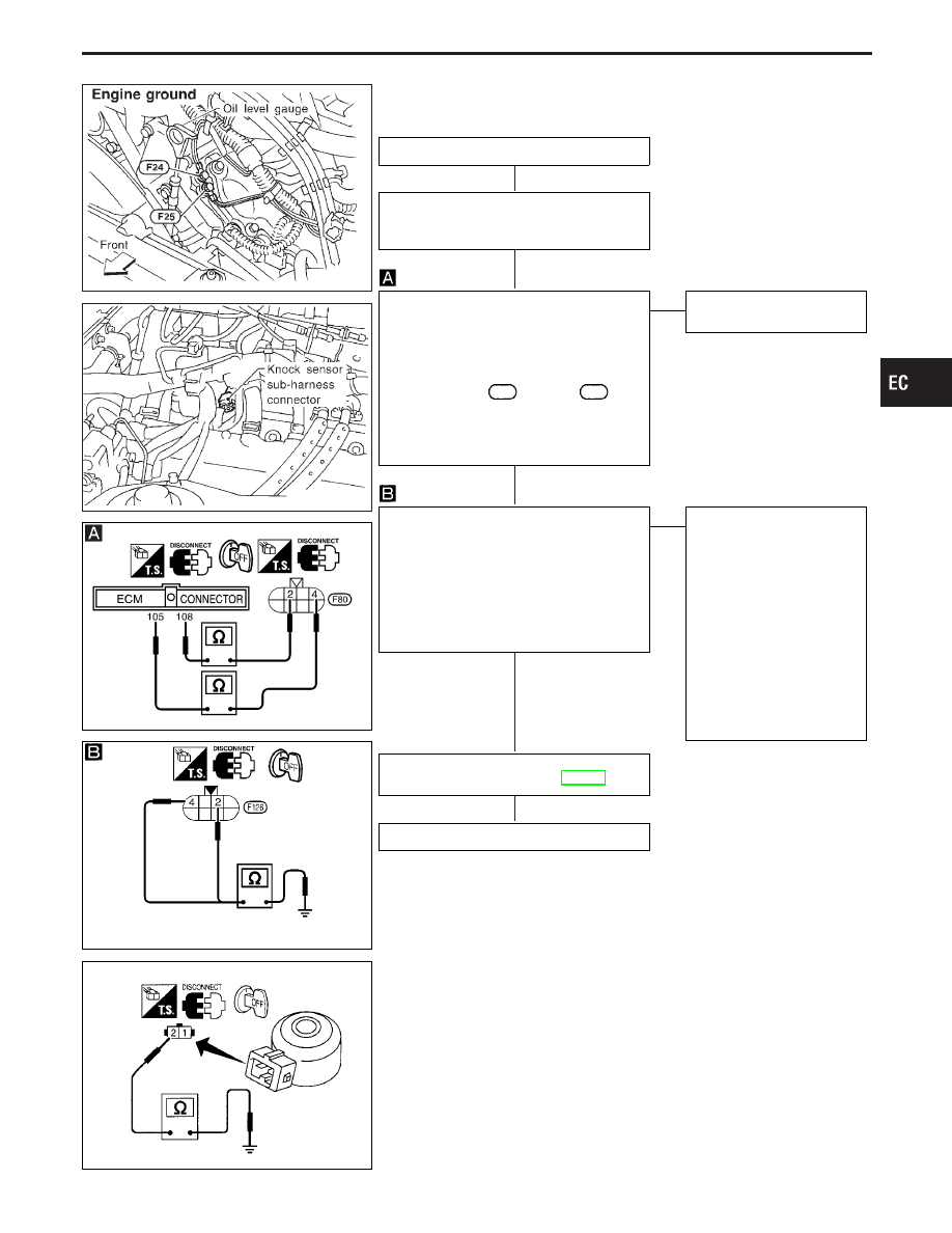
DIAGNOSTIC PROCEDURE
INSPECTION START
1. Turn ignition switch “OFF”.
2. Loosen and retighten engine ground
screws.
CHECK INPUT SIGNAL CIRCUIT-1.
1. Disconnect ECM harness connector
and knock sensor sub-harness connec-
tor.
2. Check harness continuity between ter-
minal
q
4
(bank 1),
q
2
(bank 2) and
ECM terminal
105
(bank 1),
108
(bank 2).
Continuity should exist.
If OK, check harness for short to ground
and short to power.
OK
E
NG
Repair harness or connec-
tors.
CHECK INPUT SIGNAL CIRCUIT-2.
Check harness continuity between terminal
q
4
(bank 1),
q
2
(bank 2) and engine
ground.
Continuity should exist.
If OK, check harness for short to ground
and short to power.
It is necessary to use an ohmmeter
which can measure more than 10 M
Ω
.
OK
E
NG
Check the following.
I
Harness for open or short
between knock sensor
sub-harness connector-2
and knock sensor
If NG, repair open circuit or
short to ground or short to
power in harness or con-
nectors.
I
As for knock sensor
(COMPONENT
INSPECTION), refer to
below.
If NG, replace knock sen-
sor.
Perform “TROUBLE DIAGNOSIS FOR
INTERMITTENT INCIDENT”, EC-117.
INSPECTION END
SEF546P
COMPONENT INSPECTION
Knock sensor
1.
Disconnect knock sensor harness connector.
2.
Check resistance between terminal
q
2
and ground.
Approximately 500 - 620 k
Ω
[at 25°C (77°F)]
I
It is necessary to use an ohmmeter which can measure more
than 10 M
Ω
.
CAUTION:
Do not use any knock sensors that have been dropped or
physically damaged. Use a new one.
GI
MA
EM
LC
FE
AT
PD
FA
RA
BR
ST
RS
BT
HA
EL
IDX
TROUBLE DIAGNOSIS FOR DTC P0325 (B1), P0330 (B2)
Knock Sensor (KS) (P0325: Left bank), (P0330:
Right bank) (Cont’d)
H
H
H
H
H
EC-269