Infiniti Q45 (FY33). Manual - part 184
SEF575Q
SEF156I
SEF112T
q
A
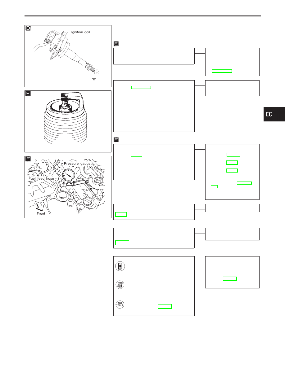
CHECK SPARK PLUGS.
Remove the spark plugs and check for
fouling, etc.
OK
E
NG
Repair or replace spark
plug(s) with standard type
one(s).
For spark plug type, refer to
“ENGINE MAINTENANCE”
in MA section.
CHECK COMPRESSION PRESSURE.
Refer to EM section.
I
Check compression pressure.
Standard:
kPa (kg/cm
2
, psi)/300 rpm
1,285 (13.1, 186)
Minimum:
kPa (kg/cm
2
, psi)/300 rpm
991 (10.1, 144)
Difference between each cylinder:
kPa (kg/cm
2
, psi)/300 rpm
98 (1.0, 14)
OK
E
NG
Check pistons, piston rings,
valves, valve seats and cyl-
inder head gaskets.
CHECK FUEL PRESSURE.
1. Release fuel pressure to zero. Refer to
page EC-37.
2. Install fuel pressure gauge and check
fuel pressure.
At idle:
Approx. 235 kPa
(2.4 kg/cm
2
, 34 psi)
OK
E
NG
Check the following.
I
Fuel pump and circuit
Refer to EC-523.
I
Fuel pressure regulator
Refer to EC-37.
I
Fuel lines
Refer to EC-38.
I
Fuel lines
Refer to “ENGINE MAIN-
TENANCE” in MA sec-
tion.
I
Fuel filter for clogging
If NG, repair or replace.
CHECK IGNITION TIMING.
Perform “BASIC INSPECTION”,
EC-91.
OK
E
NG
Adjust ignition timing.
CHECK COMPONENT
[Heated oxygen sensor 1 (front)].
Refer to “COMPONENT INSPECTION”,
EC-172.
OK
E
NG
Replace heated oxygen
sensor 1 (front).
CHECK MASS AIR FLOW SENSOR.
Check “MASS AIR FLOW” in “DATA
MONITOR” mode with CONSULT-II.
3.0 - 6.0 g
⋅
m/sec: at idling
12.9 - 25.3 g
⋅
m/sec: at 2,500 rpm
-------------------------------------------------------------------------------------------------------------------------------------- OR --------------------------------------------------------------------------------------------------------------------------------------
Check “mass air flow” in MODE 1
with GST.
3.0 - 6.0 g
⋅
m/sec: at idling
12.9 - 25.3 g
⋅
m/sec: at 2,500 rpm
-------------------------------------------------------------------------------------------------------------------------------------- OR --------------------------------------------------------------------------------------------------------------------------------------
Check mass air flow sensor output
voltage, refer to EC-131.
Approximately 2.1V: at 2,500 rpm
OK
E
NG
Check connectors for
rusted terminals or loose
connections in the mass air
flow sensor circuit or engine
grounds.
Refer to EC-124.
If NG, repair or replace it.
(Go to
q
B
on next page.)
GI
MA
EM
LC
FE
AT
PD
FA
RA
BR
ST
RS
BT
HA
EL
IDX
TROUBLE DIAGNOSIS FOR DTC P0300 - P0308
No. 1 - 8 Cylinder Misfire, Multiple Cylinder
Misfire (Cont’d)
H
H
H
H
H
H
H
EC-265