Infiniti Q45 (FY33). Manual - part 181
BANK 1
TEC791
GI
MA
EM
LC
FE
AT
PD
FA
RA
BR
ST
RS
BT
HA
EL
IDX
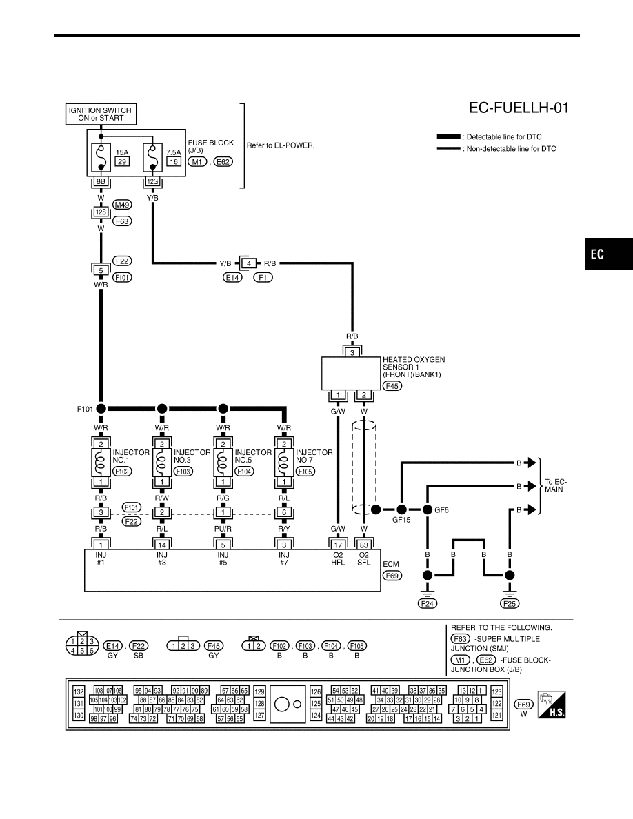
TROUBLE DIAGNOSIS FOR DTC P0172 (B1), P0175 (B2)
Fuel Injection System Function (Rich side)
(P0172: Left bank), (P0175: Right bank)
(Cont’d)
EC-253