Infiniti Q45 (FY33). Manual - part 175
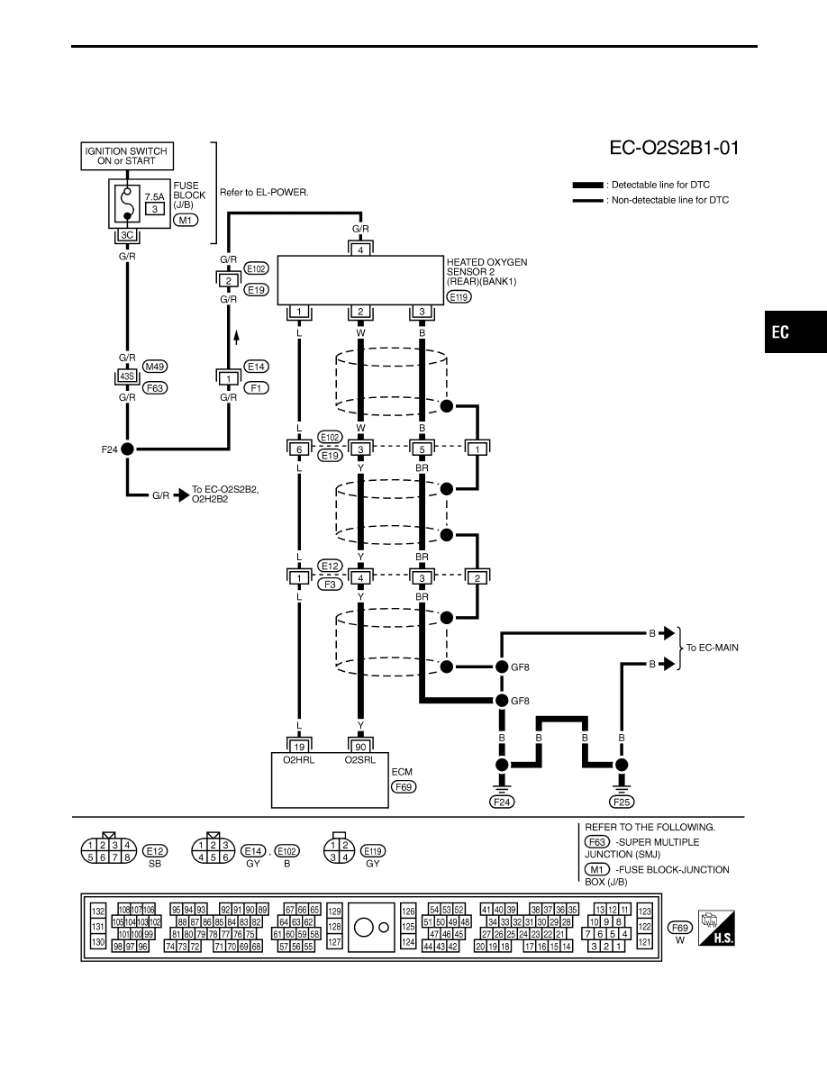
BANK 1
TEC787
GI
MA
EM
LC
FE
AT
PD
FA
RA
BR
ST
RS
BT
HA
EL
IDX
TROUBLE DIAGNOSIS FOR DTC P0139 (B1), P0159 (B2)
Heated Oxygen Sensor 2 (Rear) (P0139: Bank
1), (P0159: Bank 2) (Response Monitoring)
(Cont’d)
EC-229