Infiniti Q45 (FY33). Manual - part 149
DIAGNOSTIC TROUBLE CODE CONFIRMATION
PROCEDURE
Perform “Procedure for malfunction A” first.
If 1st trip DTC cannot be confirmed, perform “Procedure for
malfunction B”.
If there is problem in “Procedure for malfunction B”, perform
“Procedure for malfunction C”. If there is no problem on “Pro-
cedure for malfunction C”, perform “Procedure for malfunc-
tion D”.
CAUTION:
Always drive vehicle at a safe speed.
NOTE:
If “DIAGNOSTIC TROUBLE CODE CONFIRMATION PROCE-
DURE” has been previously conducted, always turn ignition
switch “OFF” and wait at least 5 seconds before conducting
the next test.
SEF399X
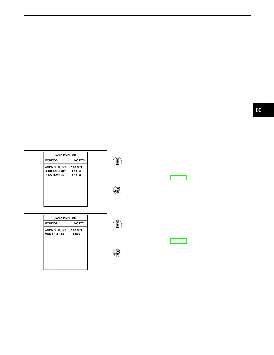
Procedure for malfunction A
1) Turn ignition switch “ON”.
2) Select “DATA MONITOR” mode with CONSULT-II.
3) Wait at least 6 seconds.
4) If 1st trip DTC is detected, go to “DIAGNOSTIC
PROCEDURE”, EC-129.
------------------------------------------------------------------------------------------------------------------------------------------------------------------------------------------------------------------------------------------------------ OR ------------------------------------------------------------------------------------------------------------------------------------------------------------------------------------------------------------------------------------------------------
Follow the procedure “With CONSULT-II” above.
SEF400X
Procedure for malfunction B
1) Turn ignition switch “ON”.
2) Select “DATA MONITOR” mode with CONSULT-II.
3) Start engine and wait 5 seconds at most.
4) If 1st trip DTC is detected, go to “DIAGNOSTIC
PROCEDURE”, EC-129.
------------------------------------------------------------------------------------------------------------------------------------------------------------------------------------------------------------------------------------------------------ OR ------------------------------------------------------------------------------------------------------------------------------------------------------------------------------------------------------------------------------------------------------
Follow the procedure “With CONSULT-II” above.
GI
MA
EM
LC
FE
AT
PD
FA
RA
BR
ST
RS
BT
HA
EL
IDX
TROUBLE DIAGNOSIS FOR DTC P0100
Mass Air Flow Sensor (MAFS) (Cont’d)
EC-125