Infiniti Q45 (FY33). Manual - part 144


  Index      Infiniti     Infiniti Q45 (FY33) - service repair manual 2001 year


Search            copyright infringement  


Content   ..  142  143  144  145   ..


Infiniti Q45 (FY33). Manual - part 144


Major Sensor Reference Graph in Data Monitor
Mode

The following are the major sensor reference graphs in “DATA MONITOR” mode.
(Select “HI SPEED” in “DATA MONITOR” with CONSULT-II.)

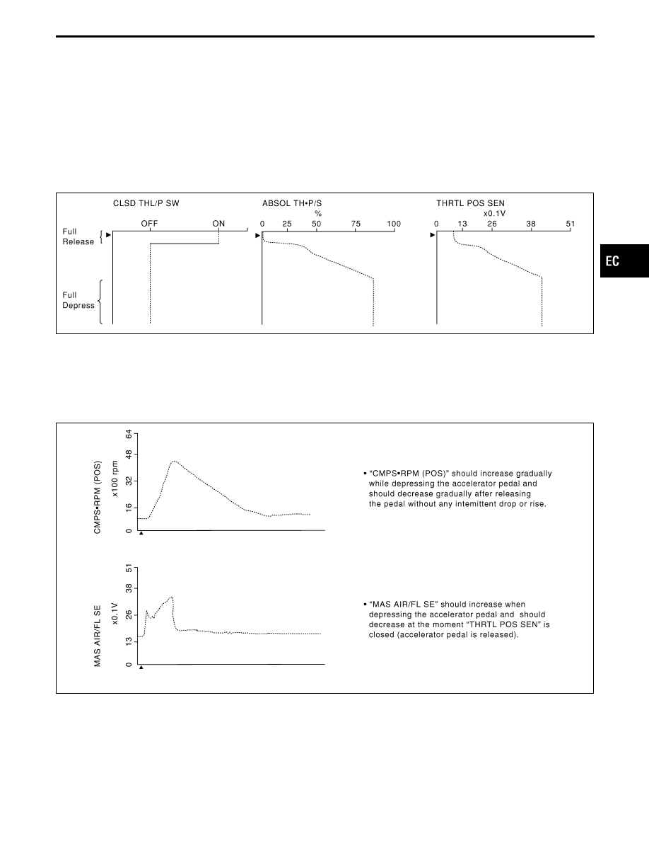
THRTL POS SEN, ABSOL TH

P/S, CLSD THL/P SW

Below is the data for “THRTL POS SEN”, “ABSOL TH

P/S” and “CLSD THL/P SW” when depressing the

accelerator pedal with the ignition switch “ON”.
The signal of “THRTL POS SEN” and “ABSOL TH

P/S” should rise gradually without any intermittent drop or

rise after “CLSD THL/P SW” is changed from “ON” to “OFF”.

SEF877X

CMPS

RPM (POS), MAS AIR/FL SE, THRTL POS SEN, HO2S2 (B1), (B2), HO2S1 (B1), (B2),

INJ PULSE

Below is the data for “CMPS

RPM (POS)”, “MAS AIR/FL SE”, “THRTL POS SEN”, “HO2S2 (B1), (B2)”, “HO2S1

(B1), (B2)” and “INJ PULSE” when revving engine quickly up to 4,800 rpm under no load after warming up
engine to normal operating temperature.
Each value is for reference, the exact value may vary.

SEF878XA

GI

MA

EM

LC

FE

AT

PD

FA

RA

BR

ST

RS

BT

HA

EL

IDX

TROUBLE DIAGNOSIS — General Description

EC-105

SEF242YA

TROUBLE DIAGNOSIS — General Description

Major Sensor Reference Graph in Data Monitor
Mode (Cont’d)

EC-106

SEF408W

ECM Terminals and Reference Value

PREPARATION

1.

ECM is located behind right side front pillar lower garnish. For
this inspection, remove the glove box.

AEC913

2.

Remove ECM harness protector.

SEF367I

3.

Perform all voltage measurements with the connectors con-
nected. Extend tester probe as shown to perform tests easily.

I

Open harness securing clip to make resting easier.

I

Use extreme care not to touch 2 pins at one time.

I

Data is for comparison and may not be exact.

ECM HARNESS CONNECTOR TERMINAL LAYOUT

SEF218U

GI

MA

EM

LC

FE

AT

PD

FA

RA

BR

ST

RS

BT

HA

EL

IDX

TROUBLE DIAGNOSIS — General Description

EC-107

ECM INSPECTION TABLE

Specification data are reference values, and are measured between each terminal and ground.

CAUTION:

Do not use ECM ground terminals when measuring voltage. Doing so may result in damage to the
ECM’s transistor. Use a ground other than ECM terminals such as the body ground.

TER-

MINAL

NO.

WIRE

COLOR

ITEM

CONDITION

DATA

(DC voltage)

1
2
3

14

4
5
6
7

R/B
R/W
R/Y
R/L
W/R
PU/R
GY/L
LG

Injector No. 1
Injector No. 8
Injector No. 7
Injector No. 3
Injector No. 6
Injector No. 5
Injector No. 4
Injector No. 2

Engine is running. (Warmed-up condition)

Idle speed

BATTERY VOLTAGE
(11 - 14V)

SEF388X

Engine is running.

Engine speed is 2,000 rpm.

BATTERY VOLTAGE
(11 - 14V)

SEF526Y

10

L/Y

EGRC-solenoid valve

Engine is running. (Warmed-up condition)

Lift up drive wheels and rev engine from idle
to 3,000 rpm in “D” position.

0 - 0.7V

Engine is running. (Warmed-up condition)

Idle speed

BATTERY VOLTAGE
(11 - 14V)

8

11

12
13

GY/L
PU
G/Y
Y

IACV-AAC valve

Engine is running.

Idle speed

0.1 - 14V

15

R/L

Fuel pump control module

Engine is cranking.

Approximately 0.4V

Engine is running.

Idle speed

Approximately 12V

16
17

L/Y
G/W

Heated oxygen sensor 1
heater (front) (bank 2)
Heated oxygen sensor 1
heater (front) (bank 1)

Engine is running.

Engine speed is below 3,200 rpm.

0 - 0.5V

Engine is running.

Engine speed is above 3,200 rpm.

BATTERY VOLTAGE
(11 - 14V)

TROUBLE DIAGNOSIS — General Description

ECM Terminals and Reference Value (Cont’d)

EC-108


Content   ..  142  143  144  145   ..