Infiniti Q45 (FY33). Manual - part 128
SEF553T
I
Method B (Using check connector)
Check the idle speed using check connector as shown in the fig-
ure. (Check connector is located in the harness protector).
SEF295T
IGNITION TIMING
Any of the following two methods may be used.
I
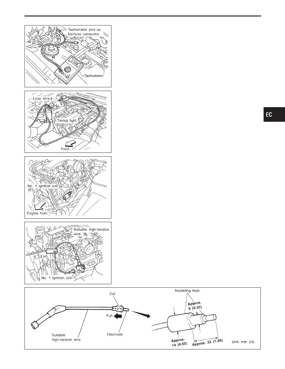
Method A
1.
Attach timing light to loop wire as shown.
2.
Check ignition timing.
SEF296T
I
Method B
1.
Remove intake air duct.
2.
Remove No. 1 ignition coil.
SEF297T
3.
Connect No. 1 ignition coil and No. 1 spark plug with suitable
high-tension wire as shown, and attach timing light clamp to
this wire.
4.
Install air duct.
5.
Check ignition timing.
SEF011V
GI
MA
EM
LC
FE
AT
PD
FA
RA
BR
ST
RS
BT
HA
EL
IDX
BASIC SERVICE PROCEDURE
Direct Ignition System — How to Check Idle
Speed and Ignition Timing (Cont’d)
EC-41