Infiniti Q45 (FY33). Manual - part 126


  Index      Infiniti     Infiniti Q45 (FY33) - service repair manual 2001 year


Search            copyright infringement  


Content   ..  124  125  126  127   ..


Infiniti Q45 (FY33). Manual - part 126


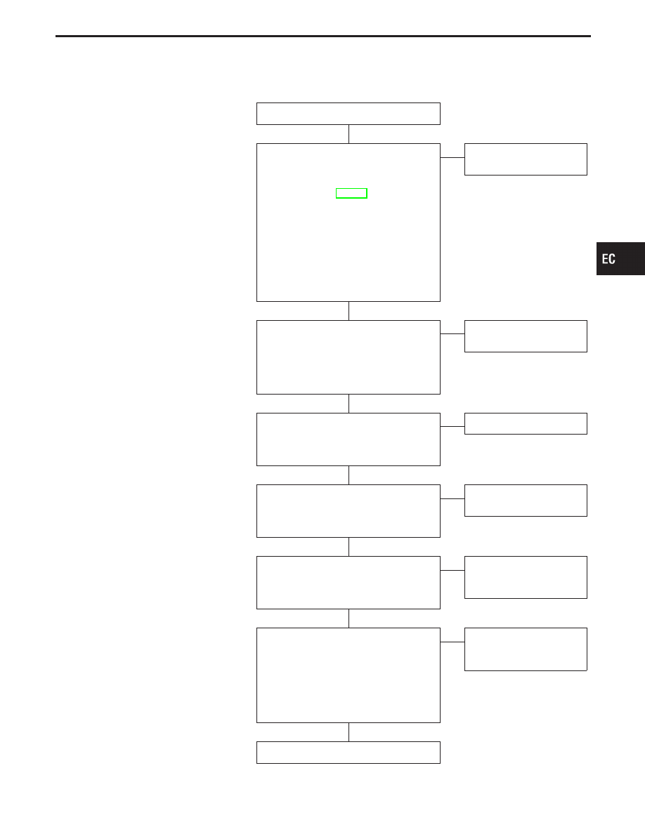
SYMPTOM: Cannot refuel/Fuel odor from the fuel filler open-

ing is strong while refueling.

INSPECTION START

CHECK COMPONENT
(Water separator and EVAP canister).
1. Check water separator for insect nests

or debris. Refer to “COMPONENT
INSPECTION”, EC-441.

2. Weigh the EVAP canister with vent con-

trol valve attached.
If the weight is:
More than 1.8 kg (4.0 lb)

NG

Less than 1.8 kg (4.0 lb)

OK

If OK, check that water drains from the
canister.
Water should not drain from the
EVAP canister.

OK

E

NG

Replace water separator or
EVAP canister.

CHECK COMPONENT
(Vent hoses and vent tubes).
Check hoses and tubes between EVAP
canister and refueling control valve for
clogging, kink, looseness and improper
connection.

OK

E

NG

Repair or replace hoses
and tubes.

CHECK COMPONENT
(Filler neck tube).
Check signal line and recirculation line for
clogging, dents and cracks.

OK

E

NG

Replace filler neck tube.

CHECK COMPONENT
(Refueling control valve).
Refer to “COMPONENT INSPECTION” on
next page.

OK

E

NG

Replace refueling control
valve with fuel tank.

CHECK COMPONENT
(Refueling EVAP vapor cut valve).
Refer to “COMPONENT INSPECTION” on
next page.

OK

E

NG

Replace fuel tank with
refueling EVAP vapor cut
valve.

CHECK COMPONENT
(Fuel filler tube).
1. Check filler neck tube and hose con-

nected to the fuel tank for clogging,
dents and cracks.

2. Check one-way fuel valve for clogging.

Refer to “COMPONENT INSPECTION”
on next page.

OK

E

NG

Replace fuel filler tube or
replace one-way fuel valve
with fuel tank.

INSPECTION END

GI

MA

EM

LC

FE

AT

PD

FA

RA

BR

ST

RS

BT

HA

EL

IDX

EVAPORATIVE EMISSION SYSTEM

On Board Refueling Vapor Recovery (ORVR)
(Cont’d)

H

H

H

H

H

H

H

EC-33

COMPONENT INSPECTION

Refueling control valve

Check refueling control valve as follows:
1. Remove fuel filler cap.
2. Check air continuity between hose ends

q

A

and

q

B

.

Blow air into the hose end

q

B

. Air should flow freely into the fuel tank.

3. Blow air into hose end

q

A

and check there is no leakage.

4. Apply pressure to both hose ends

q

A

and

q

B

[20 kPa (150 mmHg, 5.91 inHg)] using a pressure pump and

a suitable 3-way connector. And check there is no leakage.

If NG, replace refueling control valve with fuel tank.

SEF816X

SEF817X

Refueling EVAP vapor cut valve

1.

Remove fuel tank. Refer to “FUEL SYSTEM” in FE section.
Drain fuel from the tank as follows:

a. Remove fuel feed hose located on the fuel gauge

retainer.

b. Connect a spare fuel hose, one side to fuel gauge

retainer where the hose was removed and the other
side to a fuel container.

c.

Drain fuel using “FUEL PUMP RELAY” in “ACTIVE
TEST” mode with CONSULT-II.

------------------------------------------------------------------------------------------------------------------------------------------------------------------------------------------------------------------------------------------------------ OR ------------------------------------------------------------------------------------------------------------------------------------------------------------------------------------------------------------------------------------------------------

a. Remove fuel gauge retainer.
b. Drain fuel from the tank using a hand pump into a fuel

container.

2.

Check refueling EVAP vapor cut valve for being stuck to close
as follows.
Blow air into the refueling EVAP vapor cut valve (from hose
end

q

B

), and check that the air flows freely into the tank.

3.

Check EVAP vapor cut valve for being stuck to open as follow-
ing.

a.

Connect vacuum pump to hose ends

q

A

and

q

B

using a suit-

able 3-way connector.

b.

Remove fuel gauge retainer with fuel gauge unit.

Always replace O-ring with new one.

EVAPORATIVE EMISSION SYSTEM

On Board Refueling Vapor Recovery (ORVR)
(Cont’d)

EC-34

c.

Put fuel tank upside down.

d.

Apply vacuum pressure to both hose ends

q

A

and

q

B

[−13.3

kPa (−100 mmHg, −3.94 inHg)] with fuel gauge retainer
remaining open and check that the pressure is applicable.
If NG, replace refueling EVAP vapor cut valve with fuel tank.

SEF818X

One-way fuel valve

1.

Drain fuel from the tank.
Refer to “COMPONENT INSPECTION” of refueling EVAP
vapor cut valve on previous page.

2.

Remove fuel filler tube and hose.

3.

Check one-way fuel valve for operation as follows.
When pushing with finger, the valve should open; when finger
is released, the valve should shut.

Do not drop any material into the tank.

If NG, replace one-way fuel valve with fuel tank.

GI

MA

EM

LC

FE

AT

PD

FA

RA

BR

ST

RS

BT

HA

EL

IDX

EVAPORATIVE EMISSION SYSTEM

On Board Refueling Vapor Recovery (ORVR)
(Cont’d)

EC-35

Description

This system returns blow-by gas to both the intake
manifold and air cleaner.
The positive crankcase ventilation (PCV) valve is
provided to conduct crankcase blow-by gas to the
intake manifold.
During partial throttle operation of the engine, the
intake manifold sucks the blow-by gas through the
PCV valve.
Normally, the capacity of the valve is sufficient to
handle any blow-by and a small amount of ventilat-
ing air.

The ventilating air is then drawn from the air cleaner,
through the hose connecting air cleaner to rocker
cover, into the crankcase.
Under full-throttle condition, the manifold vacuum is
insufficient to draw the blow-by flow through the
valve, and its flow goes through the hose connection
in the reverse direction.
On vehicles with an excessively high blow-by some
of the flow will go through the hose connection to the
air cleaner under all conditions.

SEF110T

SEF244Q

Inspection

PCV (Positive Crankcase Ventilation) VALVE

With engine running at idle, remove ventilation hose from PCV
valve; if valve is working properly, a hissing noise will be heard as
air passes through it and a strong vacuum should be felt immedi-
ately when a finger is placed over valve inlet.

ET277

PCV HOSE

1.

Check hoses and hose connections for leaks.

2.

Disconnect all hoses and clean with compressed air. If any
hose cannot be freed of obstructions, replace.

POSITIVE CRANKCASE VENTILATION

EC-36


Content   ..  124  125  126  127   ..