Infiniti Q45 (FY33). Manual - part 101
SBR540A
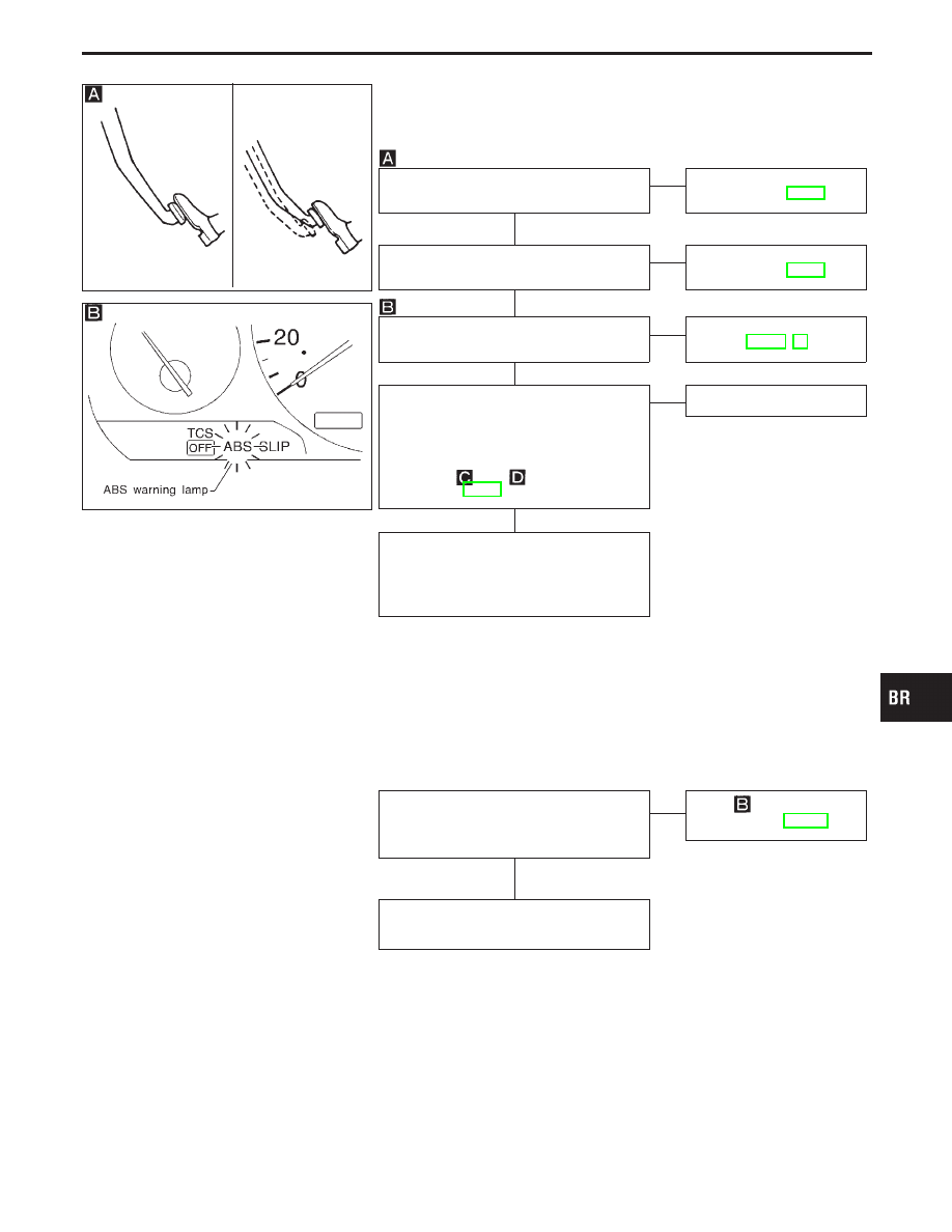
Diagnostic Procedure 29
(Unexpected pedal action)
SBR698D
Check brake pedal stroke. Is stroke
excessively large?
No
E
Yes
Perform Preliminary
Check, refer to BR-48.
Disconnect ABS actuator 8-pin connector
and check whether brake is effective.
Yes
E
No
Perform Preliminary
Check, refer to BR-48.
Ensure ABS warning lamp remains off
while driving.
OK
E
NG
Carry out self-diagnosis.
Refer to BR-59, 63.
CHECK WHEEL SENSOR.
----------------------------------------------------------------------------------------------------------------------------------------------------------------------------------------------------------------------------------------------------------------------------------------------------------------
1. Check wheel sensor connector for ter-
minal damage or loose connection.
2. Perform wheel sensor mechanical
check.
Refer to
and
in Diagnostic Pro-
cedure 7, BR-88.
OK
E
NG
Repair.
Check control unit pin terminals for dam-
age or the connection of control unit har-
ness connector.
Reconnect control unit harness connector.
Then retest.
Diagnostic Procedure 30
(Long stopping distance)
Disconnect ABS actuator 8-pin connector
and check whether stopping distance is
still long.
Yes
E
No
Go to
in Diagnostic
Procedure 29, BR-121.
Perform Preliminary Check and air bleed-
ing.
Note: Stopping distance may be larger than vehicles without
ABS when road condition is slippery.
GI
MA
EM
LC
EC
FE
AT
PD
FA
RA
ST
RS
BT
HA
EL
IDX
TROUBLE DIAGNOSES FOR SYMPTOMS
H
H
H
H
H
BR-121